Consider the liquid-level control system shown in Fig. P124. The tanks are noninteracting. The following information is
Question:
Consider the liquid-level control system shown in Fig. P12−4. The tanks are noninteracting. The following information is known:
• The resistances on the tanks are linear. These resistances were tested separately, and it was found that if the steady-state flow rate q cfm is plotted against steady-state tank level h ft, the slope of the line dq/dh is 2 ft2 /min.
• The cross-sectional area of each tank is 2 ft2.
• The control valve was tested separately, and it was found that a change of 1 psi in pressure to the valve produced a change in flow of 0.1 cfm.
• There is no dynamic lag in the valve or the measuring element.
(a) Draw a block diagram of this control system, and in each block give the transfer function, with numerical values of the parameters.
(b) Determine the controller gain Kc for a critically damped response.
(c) If the tanks were connected so that they were interacting, what is the value of Kc needed for critical damping?
(d) Using 1.5 times the value of Kc determined in part (c), determine the response of the level in tank 2 to a step-change in the set point of 1 in of level.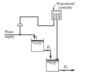
Expert Answer:
bkc for critically damped response Therefore the block diagram for the controll... View the full answer