

Problem 9 (50 Points) An air-cooled aluminum heat sink is used to keep electronics cool (see...
Fantastic news! We've Found the answer you've been seeking!
Question:
Transcribed Image Text:
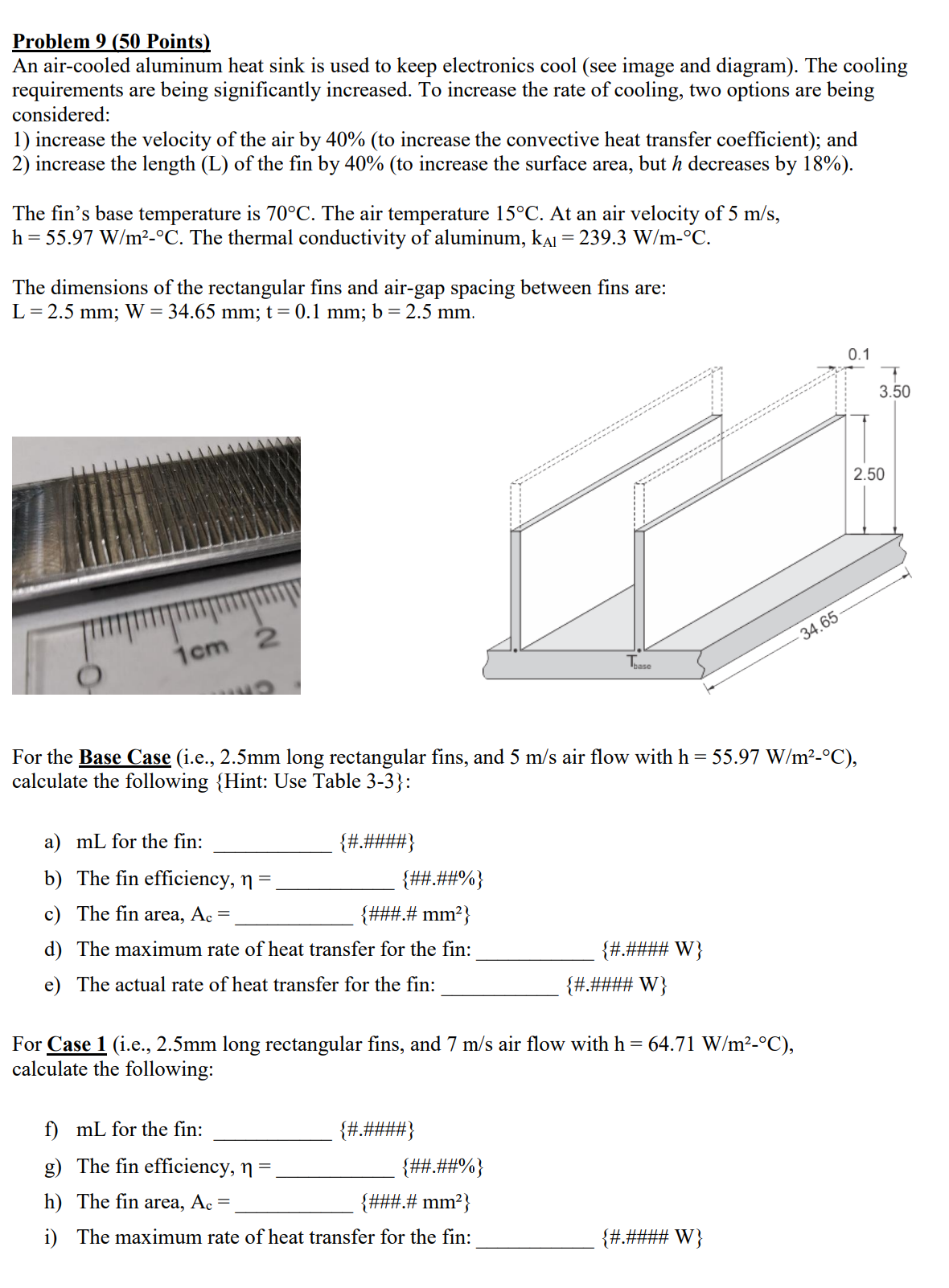
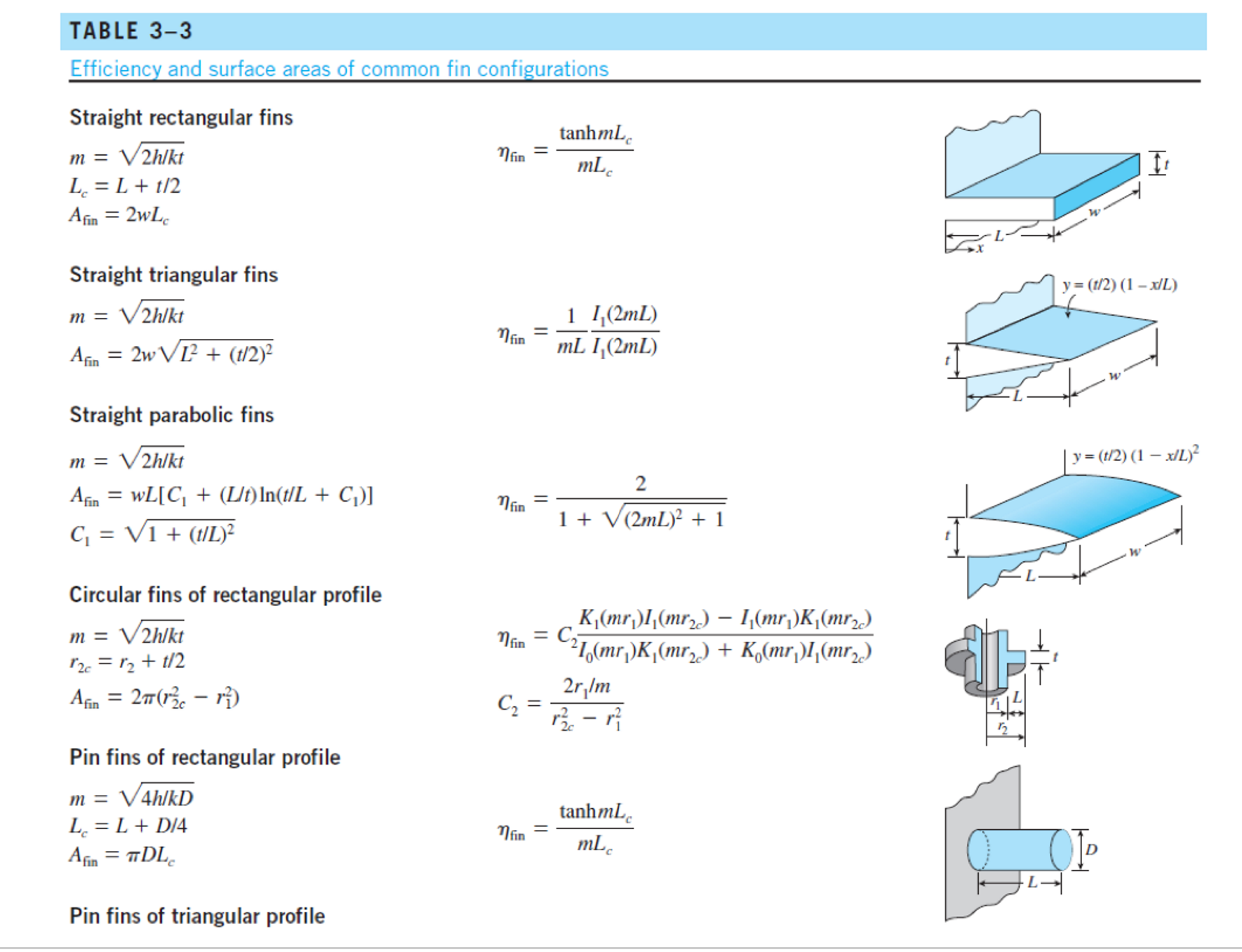
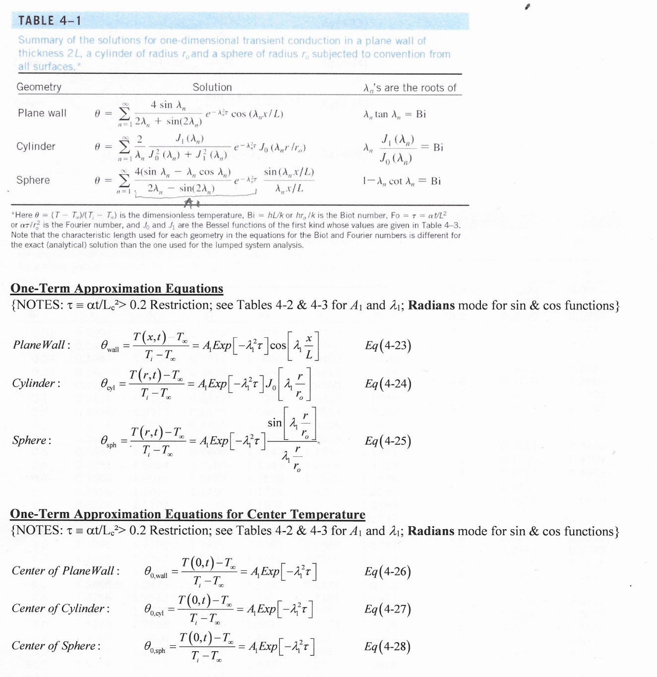
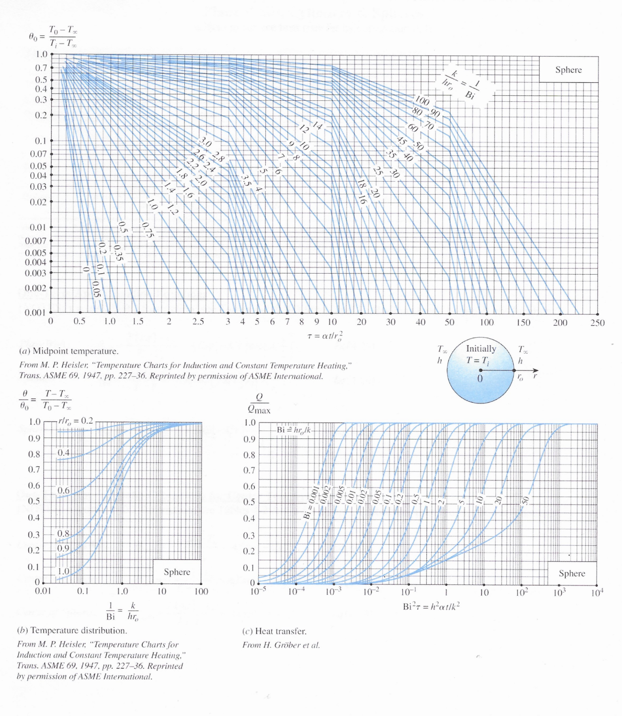
Problem 9 (50 Points) An air-cooled aluminum heat sink is used to keep electronics cool (see image and diagram). The cooling requirements are being significantly increased. To increase the rate of cooling, two options are being considered: 1) increase the velocity of the air by 40% (to increase the convective heat transfer coefficient); and 2) increase the length (L) of the fin by 40% (to increase the surface area, but h decreases by 18%). The fin's base temperature is 70C. The air temperature 15C. At an air velocity of 5 m/s, h=55.97 W/m-C. The thermal conductivity of aluminum, k = 239.3 W/m-C. The dimensions of the rectangular fins and air-gap spacing between fins are: L = 2.5 mm; W = 34.65 mm; t = 0.1 mm; b = 2.5 mm. 1cm 2 Tease 34.65 For the Base Case (i.e., 2.5mm long rectangular fins, and 5 m/s air flow with h = 55.97 W/m-C), calculate the following {Hint: Use Table 3-3}: a) mL for the fin: {#.####} b) The fin efficiency, n = {##.##%} c) The fin area, Ac =. {###.# mm} d) The maximum rate of heat transfer for the fin: {#.#### W} e) The actual rate of heat transfer for the fin: {#.#### W} For Case 1 (i.e., 2.5mm long rectangular fins, and 7 m/s air flow with h = 64.71 W/m-C), calculate the following: f) mL for the fin: {#.####} g) The fin efficiency, n = {##.##%} h) The fin area, Ac = {###.# mm} i) The maximum rate of heat transfer for the fin: {#.#### W} 0.1 3.50 2.50 j) The actual rate of heat transfer for the fin: {#.#### W} k) The increase in the actual rate of heat transfer (i.e., (J - E)/E *100): For Case 2 (i.e., 3.5mm long rectangular fins, and 5 m/s air flow with h = 47.30 W/m-C), calculate the following: 1) mL for the fin: {##.##%} {#.####} m) The fin efficiency, n = {##.##%} n) The fin area, Ac =. {###.# mm} o) The maximum rate of heat transfer for the fin: p) The actual rate of heat transfer for the fin: {#.#### W} {#.#### W} q) The increase in the actual rate of heat transfer (i.e., (P - E)/E *100): Based on your analysis which method yields the better increase in cooling capacity? Case 1: Increase the air flow through the fin array. Case 2: Increase the length of the fins to increase heat transfer surface area (even though h went down by 18%). {##.##%} TABLE 3-3 Efficiency and surface areas of common fin configurations Straight rectangular fins m = V2h/kt L = L + 1/2 tanhmL nfin = mL Afin = 2wLc Straight triangular fins m = V2h/kt y= (1/2) (1-x/L) nfin Afin = 2w L + (t/2) 1 I(2mL) mL I(2mL) w Straight parabolic fins y = (t/2) (1 - x/L) m = V2hlkt 2 Afin = WL[C + (L/t) In(t/L + C)] nfin 1 + V (2mL) + 1 t C = 1 + (1/L) Circular fins of rectangular profile m = V2h/kt 12c = 12 + 1/2 Afin = 2 (1-1) Pin fins of rectangular profile m = 4h/kD L = L+D/4 Afin = DLC Pin fins of triangular profile K(mr)I(mr) I(mr)K(mr2) 21(mr)K(mr) + K(mr)I(mr) nfin = C 2r/m C = tanhmL = Mfin mLc 12 Pin fins of triangular profile 2 I(2mL) nfin mL I(2mL) 12(x) = 10 (x) - (2/x)I (x) where x = 2mL y = (D/2) (1-x/L) 2 1 + (2mL/3) + 1 m = 4h/kD D = 1 + (D/2) 2 Afin Pin fins of parabolic profile m = 4h/kD L Aim = TDIC,C4 - In(2DC /L + C)] An 8D C3 = 1 + 2(D/L) C = 1 + (DIL) 2D Pin fins of parabolic profile (blunt tip) m = 4h/kD Afin = D4 961 {[16(L/D) + 1]/2 nfin 2- 1} nfin = 3 12(4mL/3) 2mL 10(4mL/3) y= (D/2) (1-x/L) y = (D/2) (1-x/L)1/2 TABLE 4-1 Summary of the solutions for one-dimensional transient conduction in a plane wall of thickness 2L, a cylinder of radius r, and a sphere of radius r. subjected to convention from all surfaces.* A's are the roots of Geometry Solution 4 sin A, Plane wall 0 = e-cos (Ax/L) A,, tan A,, = Bi 2A + sin(2A) 2 J(AR) J(A) Cylinder 0 = e-Jo (Arr) = Bi A J (A) + J} (A) Jo (Am) 4(sin A - A cos ) Sphere 0 = e-== 2A, sin (A,,x/L) Ax/L 1-A,, cot A, Bi sin(2A) AL *Here @ (TT)/(TT) is the dimensionless temperature, BihL/k or hr, /k is the Biot number, Fo= T = at/L or ar/r2 is the Fourier number, and Jo and J are the Bessel functions of the first kind whose values are given in Table 4-3. Note that the characteristic length used for each geometry in the equations for the Biot and Fourier numbers is different for the exact (analytical) solution than the one used for the lumped system analysis. One-Term Approximation Equations {NOTES: = at/Lc2> 0.2 Restriction; see Tables 4-2 & 4-3 for A and 21; Radians mode for sin & cos functions} Plane Wall: 0. = T(x,t)-Tx wall T-T = A,Exp[-]cos ]00[4] Eq(4-23) Cylinder: Ocvl = T(r,t)-T T-T = 4, Exp [1}t] J [1, Eq(4-24) r sin T(r.)-T-A Exp[-] Sphere: sph T-T Eq(4-25) r ro One-Term Approximation Equations for Center Temperature {NOTES: t = at/Lc> 0.2 Restriction; see Tables 4-2 & 4-3 for 41 and 21; Radians mode for sin & cos functions} Center of Plane Wall: Center of Cylinder: Center of Sphere: T(0.1)-T = AExp[-] Eq(4-26) 00,wall T-T T(0,1)-T = A Exp[-x+] Eq(4-27) 00,cyl T-T T(0,t)-T AExp[-2] Eq(4-28) 00,sph T-T One-Term Approximation Equations for Fraction of Maximum Possible Heat Transfer {NOTES: Tat/Le2> 0.2 Restriction; see Tables 4-2 & 4-3 for A and 21; Radians mode for sin & cos functions} sin() 215 Q Plane Wall: =1-00,wall Eq(4-33) Qmax wall Q J(2) Cylinder: =1-200.cyl Eq(4-34) max cyl Q Sphere: =1-30 0,sphi Qmax sin()- cos(4) 23 Eq (4-35) sph 2max =mc(T-T)= pvc (T-T) Eq (4-30) TABLE 4-2 Coefficients used in the one-term approximate solution of transient one- dimensional heat conduction in plane walls, cylinders, and spheres (Bi = huk for a plane wall of thickness 2L, and Bi=hrolk for a cylinder or sphere of radius ro) TABLE 4-3 The zeroth- and first-order Bessel functions of the first kind n Jo(n) J(n) 0.0 1.0000 0.0000 Plane Wall Cylinder Sphere 0.1 Bi A 0.01 0.0998 1.0017 0.02 0.1410 1.0033 0.04 0.1987 1.0066 0.06 0.2425 1.0098 0.08 0.2791 1.0130 A A 0.1412 1.0025 0.1730 0.1995 1.0050 0.2445 A 0.2 1.0030 0.3 1.0060 0.4 7234 0.9975 0.0499 0.9900 0.0995 0.9776 0.1483 0.9604 0.1960 0.2814 1.0099 0.3450 1.0120 0.3438 1.0148 0.4217 0.5 1.0179 0.9385 0.2423 0.3960 1.0197 0.4860 1.0239 0.6 0.9120 0.2867 0.1 0.3111 1.0161 0.4417 1.0246 0.5423 1.0298 0.7 0.8812 0.3290 0.2 0.4328 1.0311 0.6170 1.0483 0.7593 1.0592 0.8 0.8463 0.3688 0.3 0.5218 1.0450 0.7465 1.0712 0.9208 1.0880 0.9 0.8075 0.4059 0.4 0.5932 1.0580 0.8516 1.0931 1.0528 1.1164 0.5 0.6533 1.0701 0.9408 1.0 1.1143 0.7652 0.4400 1.1656 1.1441 0.6 0.7051 1.0814 1.0184 1.1 1.1345 0.7196 1.2644 1.1713 0.4709 0.7 0.7506 1.0918 1.2 1.0873 0.6711 1.1539 1.3525 1.1978 0.4983 0.8 0.7910 1.1016 1.3 1.1490 0.6201 1.1724 0.5220 0.9 0.8274 1.1107 1.2048 1.0 0.8603 1.1191 1.2558 2.0 1.0769 1.1785 1.5995 1.4320 1.1902 1.5044 1.2488 1.2071 1.5708 1.2732 1.3384 2.0288 1.2236 1.4 0.5669 0.5419 1.5 0.5118 0.5579 1.4793 1.6 0.4554 0.5699 3.0 1.1925 1.2102 1.7887 1.4191 2.2889 1.6227 1.7 0.3980 0.5778 4.0 1.2646 1.2287 1.9081 1.4698 2.4556 1.7202 1.8 0.3400 0.5815 5.0 1.3138 1.2403 1.9898 1.5029 2.5704 1.7870 1.9 0.2818 0.5812 6.0 1.3496 1.2479 2.0490 1.5253 2.6537 1.8338 7.0 1.3766 1.2532 2.0937 1.5411 2.7165 1.8673 2.0 0.2239 0.5767 8.0 1.3978 1.2570 2.1286 1.5526 2.7654 1.8920 2.1 0.1666 0.5683 9.0 1.4149 1.2598 2.1566 1.5611 2.8044 1.9106 2.2 0.1104 0.5560 10.0 1.4289 1.2620 2.1795 1.5677 2.8363 1.9249 2.3 0.0555 0.5399 20.0 1.4961 1.2699 2.2880 30.0 1.5202 1.2717 2.3261 40.0 50.0 100.0 00 1.5919 1.5973 3.0372 1.9898 1.5325 1.2723 2.3455 1.5993 3.0632 1.9942 1.5400 1.2727 2.3572 1.6002 3.0788 1.9962 1.5552 1.2731 2.3809 1.6015 3.1102 1.5708 1.2732 2.4048 1.6021 3.1416 2.9857 1.9781 2.4 0.0025 0.5202 2.6 -0.0968 0.4708 2.8 -0.1850 0.4097 1.9990 3.0 -0.2601 0.3391 2.0000 3.2 -0.3202 0.2613 NOTE: Tat/L> 0.2 Restriction for 1-term approximation. To-Tx 00 = T-T 1.0 0.7 0.5+ 0.4+ 0.3 0.2 0.1 0.07 0.05 0.04 0.03 1.0 0.7 0.5 0.8 0.6: 6 14 k 1 hL Bi 10 9 8 25 100 90 80 ++70 60 45-50 35 40' Plate 0.02 20.4 S 8 0.01 18.30 0.007 0.005 0.004 0.003 0.002 1 0.001 0 1 2 3 46810 14 18 22 26 30 50 70 100 120 150 300 400 500 600 700 T = t/L (a) Midplane temperature. From M. P. Heisler, "Temperature Charts for Induction and Constant Temperature Heating," Trans. ASME 69, 1947, pp. 227-36. Reprinted by permission of ASME International. Tx Initially T h T = Ti h 0 L 1 2L # == 80 T-T To-Tx 1.0 x/L = 0.2 Qmax 1.0 0.9 0.9 Bi=hL/k 0.4 0.8 0.8 0.7 0.7 0.6 0.6 0.6 0.5 0.5 0.002: 0.4 0.8 0.4 0.3 0.3 0.9 0.2 0.2 0.1 1.0 0.1 Plate 0 Plate 0 0.01 0.1 1.0 10 100 10-5 10-4 10-3 10-2 10-1 1 10 102 103 10+ 1 k Bir = hatlk = Bi hL (b) Temperature distribution. From M. P. Heisler, "Temperature Charts for Induction and Constant Temperature Heating," Trans. ASME 69, 1947, pp. 227-36. Reprinted by permission of ASME International. (c) Heat transfer. From H. Grber et al. To-Tx T-T% 00 = 1.0 0.7 0.5 0.4 0.3 0.2 0.1 0.07 0.05 0.04 0.03 0.02 0.01 0.007 0.005 0.004 0.003 0.002 3.5 2.5 1.8 1.42 1.0 1.6 0 e Bi hro 100 90 70-80. 50 40 60 45 25 20 18 16. 14. 12 10 30 Cylinder 0.001 0 1 2 3 46810 14 18 22 26 30 50 70 100 120 140 150 250 350 T = atir (a) Centerline temperature. From M. P. Heisler, "Temperature Charts for Induction and Constant Temperature Heating," Trans. ASME 69, 1947, pp. 227-36. Reprinted by permission of ASME International. h T Initially T T=T h 0 ro T-Tx = 80 To-T% Qmax 1.0 rlr=0.2 1.0 Bi=hrlk 0.9 0.9 10.4 0.8 0.8 0.7 0.7 0.6 -0.6- 0.6 0.5 0.5 100'0 = 0.002 .005 0.01 B 0.4 0.4 0.8 0.3 0.3 0.2 -0.9 0.2 0.1 = 0.1 1.0 Cylinder Cylinder 0 0 0.01 0.1 1.0 10 100 10-5 10-4 10-3 10-2 10-1 1 10 10 103 10+ 1 k Bir=hatlk = Bi hro (b) Temperature distribution. From M. P. Heisler, "Temperature Charts for Induction and Constant Temperature Heating," Trans. ASME 69, 1947, pp. 227-36. Reprinted by permission of ASME International. (c) Heat transfer. From H. Grber et al. 80= 1.0 To-Tx T-T 0.7 0.5 0.4 0.3 0.2 0.1 0.07 0.05 0.04 0.03 0.02 1.0 3.0 2.8 2.6 2.4 2.2 2.0 1.8 A 1.6 k hro - Bi 100 90 80 70 60 50 45 40 35 14 30 Sphere 0.01 0.007 0.005 0.004 0.003 0.002 5 0.001 0 0.5 1.0 1.5 2 2.5 3 4 5 6 78 9 10 20 30 40 50 100 150 200 250 T = atr (a) Midpoint temperature. From M. P. Heisler, "Temperature Charts for Induction and Constant Temperature Heating," Trans. ASME 69, 1947, pp. 227-36. Reprinted by permission of ASME International. Tx h Initially T=T Tx h 0 % r Q Qmax 1.0 Bi=hrolk 0.9 0.8 0.7 0.6 0.5 - 12 | 0.4 B 0.3 0.2 0.1 Sphere 0. 100 10-5 10-4 10-3 10-2 10-1 1 10 10 103 10+ Bir=hat/k T-T = 00 To-Tx 1.0 rlr = 0.2 0.9 0.8 -0.4. 0.7 0.6 0.6 0.5 0.4 0.3 0.8 0.2 0.9 0.1 1.0 0 0.01 0.1 1.0 10 1 = Bi k hr Sphere (b) Temperature distribution. From M. P. Heisler, "Temperature Charts for Induction and Constant Temperature Heating," Trans. ASME 69, 1947, pp. 227-36. Reprinted by permission of ASME International. (c) Heat transfer. From H. Grber et al. Problem 9 (50 Points) An air-cooled aluminum heat sink is used to keep electronics cool (see image and diagram). The cooling requirements are being significantly increased. To increase the rate of cooling, two options are being considered: 1) increase the velocity of the air by 40% (to increase the convective heat transfer coefficient); and 2) increase the length (L) of the fin by 40% (to increase the surface area, but h decreases by 18%). The fin's base temperature is 70C. The air temperature 15C. At an air velocity of 5 m/s, h=55.97 W/m-C. The thermal conductivity of aluminum, k = 239.3 W/m-C. The dimensions of the rectangular fins and air-gap spacing between fins are: L = 2.5 mm; W = 34.65 mm; t = 0.1 mm; b = 2.5 mm. 1cm 2 Tease 34.65 For the Base Case (i.e., 2.5mm long rectangular fins, and 5 m/s air flow with h = 55.97 W/m-C), calculate the following {Hint: Use Table 3-3}: a) mL for the fin: {#.####} b) The fin efficiency, n = {##.##%} c) The fin area, Ac =. {###.# mm} d) The maximum rate of heat transfer for the fin: {#.#### W} e) The actual rate of heat transfer for the fin: {#.#### W} For Case 1 (i.e., 2.5mm long rectangular fins, and 7 m/s air flow with h = 64.71 W/m-C), calculate the following: f) mL for the fin: {#.####} g) The fin efficiency, n = {##.##%} h) The fin area, Ac = {###.# mm} i) The maximum rate of heat transfer for the fin: {#.#### W} 0.1 3.50 2.50 j) The actual rate of heat transfer for the fin: {#.#### W} k) The increase in the actual rate of heat transfer (i.e., (J - E)/E *100): For Case 2 (i.e., 3.5mm long rectangular fins, and 5 m/s air flow with h = 47.30 W/m-C), calculate the following: 1) mL for the fin: {##.##%} {#.####} m) The fin efficiency, n = {##.##%} n) The fin area, Ac =. {###.# mm} o) The maximum rate of heat transfer for the fin: p) The actual rate of heat transfer for the fin: {#.#### W} {#.#### W} q) The increase in the actual rate of heat transfer (i.e., (P - E)/E *100): Based on your analysis which method yields the better increase in cooling capacity? Case 1: Increase the air flow through the fin array. Case 2: Increase the length of the fins to increase heat transfer surface area (even though h went down by 18%). {##.##%} TABLE 3-3 Efficiency and surface areas of common fin configurations Straight rectangular fins m = V2h/kt L = L + 1/2 tanhmL nfin = mL Afin = 2wLc Straight triangular fins m = V2h/kt y= (1/2) (1-x/L) nfin Afin = 2w L + (t/2) 1 I(2mL) mL I(2mL) w Straight parabolic fins y = (t/2) (1 - x/L) m = V2hlkt 2 Afin = WL[C + (L/t) In(t/L + C)] nfin 1 + V (2mL) + 1 t C = 1 + (1/L) Circular fins of rectangular profile m = V2h/kt 12c = 12 + 1/2 Afin = 2 (1-1) Pin fins of rectangular profile m = 4h/kD L = L+D/4 Afin = DLC Pin fins of triangular profile K(mr)I(mr) I(mr)K(mr2) 21(mr)K(mr) + K(mr)I(mr) nfin = C 2r/m C = tanhmL = Mfin mLc 12 Pin fins of triangular profile 2 I(2mL) nfin mL I(2mL) 12(x) = 10 (x) - (2/x)I (x) where x = 2mL y = (D/2) (1-x/L) 2 1 + (2mL/3) + 1 m = 4h/kD D = 1 + (D/2) 2 Afin Pin fins of parabolic profile m = 4h/kD L Aim = TDIC,C4 - In(2DC /L + C)] An 8D C3 = 1 + 2(D/L) C = 1 + (DIL) 2D Pin fins of parabolic profile (blunt tip) m = 4h/kD Afin = D4 961 {[16(L/D) + 1]/2 nfin 2- 1} nfin = 3 12(4mL/3) 2mL 10(4mL/3) y= (D/2) (1-x/L) y = (D/2) (1-x/L)1/2 TABLE 4-1 Summary of the solutions for one-dimensional transient conduction in a plane wall of thickness 2L, a cylinder of radius r, and a sphere of radius r. subjected to convention from all surfaces.* A's are the roots of Geometry Solution 4 sin A, Plane wall 0 = e-cos (Ax/L) A,, tan A,, = Bi 2A + sin(2A) 2 J(AR) J(A) Cylinder 0 = e-Jo (Arr) = Bi A J (A) + J} (A) Jo (Am) 4(sin A - A cos ) Sphere 0 = e-== 2A, sin (A,,x/L) Ax/L 1-A,, cot A, Bi sin(2A) AL *Here @ (TT)/(TT) is the dimensionless temperature, BihL/k or hr, /k is the Biot number, Fo= T = at/L or ar/r2 is the Fourier number, and Jo and J are the Bessel functions of the first kind whose values are given in Table 4-3. Note that the characteristic length used for each geometry in the equations for the Biot and Fourier numbers is different for the exact (analytical) solution than the one used for the lumped system analysis. One-Term Approximation Equations {NOTES: = at/Lc2> 0.2 Restriction; see Tables 4-2 & 4-3 for A and 21; Radians mode for sin & cos functions} Plane Wall: 0. = T(x,t)-Tx wall T-T = A,Exp[-]cos ]00[4] Eq(4-23) Cylinder: Ocvl = T(r,t)-T T-T = 4, Exp [1}t] J [1, Eq(4-24) r sin T(r.)-T-A Exp[-] Sphere: sph T-T Eq(4-25) r ro One-Term Approximation Equations for Center Temperature {NOTES: t = at/Lc> 0.2 Restriction; see Tables 4-2 & 4-3 for 41 and 21; Radians mode for sin & cos functions} Center of Plane Wall: Center of Cylinder: Center of Sphere: T(0.1)-T = AExp[-] Eq(4-26) 00,wall T-T T(0,1)-T = A Exp[-x+] Eq(4-27) 00,cyl T-T T(0,t)-T AExp[-2] Eq(4-28) 00,sph T-T One-Term Approximation Equations for Fraction of Maximum Possible Heat Transfer {NOTES: Tat/Le2> 0.2 Restriction; see Tables 4-2 & 4-3 for A and 21; Radians mode for sin & cos functions} sin() 215 Q Plane Wall: =1-00,wall Eq(4-33) Qmax wall Q J(2) Cylinder: =1-200.cyl Eq(4-34) max cyl Q Sphere: =1-30 0,sphi Qmax sin()- cos(4) 23 Eq (4-35) sph 2max =mc(T-T)= pvc (T-T) Eq (4-30) TABLE 4-2 Coefficients used in the one-term approximate solution of transient one- dimensional heat conduction in plane walls, cylinders, and spheres (Bi = huk for a plane wall of thickness 2L, and Bi=hrolk for a cylinder or sphere of radius ro) TABLE 4-3 The zeroth- and first-order Bessel functions of the first kind n Jo(n) J(n) 0.0 1.0000 0.0000 Plane Wall Cylinder Sphere 0.1 Bi A 0.01 0.0998 1.0017 0.02 0.1410 1.0033 0.04 0.1987 1.0066 0.06 0.2425 1.0098 0.08 0.2791 1.0130 A A 0.1412 1.0025 0.1730 0.1995 1.0050 0.2445 A 0.2 1.0030 0.3 1.0060 0.4 7234 0.9975 0.0499 0.9900 0.0995 0.9776 0.1483 0.9604 0.1960 0.2814 1.0099 0.3450 1.0120 0.3438 1.0148 0.4217 0.5 1.0179 0.9385 0.2423 0.3960 1.0197 0.4860 1.0239 0.6 0.9120 0.2867 0.1 0.3111 1.0161 0.4417 1.0246 0.5423 1.0298 0.7 0.8812 0.3290 0.2 0.4328 1.0311 0.6170 1.0483 0.7593 1.0592 0.8 0.8463 0.3688 0.3 0.5218 1.0450 0.7465 1.0712 0.9208 1.0880 0.9 0.8075 0.4059 0.4 0.5932 1.0580 0.8516 1.0931 1.0528 1.1164 0.5 0.6533 1.0701 0.9408 1.0 1.1143 0.7652 0.4400 1.1656 1.1441 0.6 0.7051 1.0814 1.0184 1.1 1.1345 0.7196 1.2644 1.1713 0.4709 0.7 0.7506 1.0918 1.2 1.0873 0.6711 1.1539 1.3525 1.1978 0.4983 0.8 0.7910 1.1016 1.3 1.1490 0.6201 1.1724 0.5220 0.9 0.8274 1.1107 1.2048 1.0 0.8603 1.1191 1.2558 2.0 1.0769 1.1785 1.5995 1.4320 1.1902 1.5044 1.2488 1.2071 1.5708 1.2732 1.3384 2.0288 1.2236 1.4 0.5669 0.5419 1.5 0.5118 0.5579 1.4793 1.6 0.4554 0.5699 3.0 1.1925 1.2102 1.7887 1.4191 2.2889 1.6227 1.7 0.3980 0.5778 4.0 1.2646 1.2287 1.9081 1.4698 2.4556 1.7202 1.8 0.3400 0.5815 5.0 1.3138 1.2403 1.9898 1.5029 2.5704 1.7870 1.9 0.2818 0.5812 6.0 1.3496 1.2479 2.0490 1.5253 2.6537 1.8338 7.0 1.3766 1.2532 2.0937 1.5411 2.7165 1.8673 2.0 0.2239 0.5767 8.0 1.3978 1.2570 2.1286 1.5526 2.7654 1.8920 2.1 0.1666 0.5683 9.0 1.4149 1.2598 2.1566 1.5611 2.8044 1.9106 2.2 0.1104 0.5560 10.0 1.4289 1.2620 2.1795 1.5677 2.8363 1.9249 2.3 0.0555 0.5399 20.0 1.4961 1.2699 2.2880 30.0 1.5202 1.2717 2.3261 40.0 50.0 100.0 00 1.5919 1.5973 3.0372 1.9898 1.5325 1.2723 2.3455 1.5993 3.0632 1.9942 1.5400 1.2727 2.3572 1.6002 3.0788 1.9962 1.5552 1.2731 2.3809 1.6015 3.1102 1.5708 1.2732 2.4048 1.6021 3.1416 2.9857 1.9781 2.4 0.0025 0.5202 2.6 -0.0968 0.4708 2.8 -0.1850 0.4097 1.9990 3.0 -0.2601 0.3391 2.0000 3.2 -0.3202 0.2613 NOTE: Tat/L> 0.2 Restriction for 1-term approximation. To-Tx 00 = T-T 1.0 0.7 0.5+ 0.4+ 0.3 0.2 0.1 0.07 0.05 0.04 0.03 1.0 0.7 0.5 0.8 0.6: 6 14 k 1 hL Bi 10 9 8 25 100 90 80 ++70 60 45-50 35 40' Plate 0.02 20.4 S 8 0.01 18.30 0.007 0.005 0.004 0.003 0.002 1 0.001 0 1 2 3 46810 14 18 22 26 30 50 70 100 120 150 300 400 500 600 700 T = t/L (a) Midplane temperature. From M. P. Heisler, "Temperature Charts for Induction and Constant Temperature Heating," Trans. ASME 69, 1947, pp. 227-36. Reprinted by permission of ASME International. Tx Initially T h T = Ti h 0 L 1 2L # == 80 T-T To-Tx 1.0 x/L = 0.2 Qmax 1.0 0.9 0.9 Bi=hL/k 0.4 0.8 0.8 0.7 0.7 0.6 0.6 0.6 0.5 0.5 0.002: 0.4 0.8 0.4 0.3 0.3 0.9 0.2 0.2 0.1 1.0 0.1 Plate 0 Plate 0 0.01 0.1 1.0 10 100 10-5 10-4 10-3 10-2 10-1 1 10 102 103 10+ 1 k Bir = hatlk = Bi hL (b) Temperature distribution. From M. P. Heisler, "Temperature Charts for Induction and Constant Temperature Heating," Trans. ASME 69, 1947, pp. 227-36. Reprinted by permission of ASME International. (c) Heat transfer. From H. Grber et al. To-Tx T-T% 00 = 1.0 0.7 0.5 0.4 0.3 0.2 0.1 0.07 0.05 0.04 0.03 0.02 0.01 0.007 0.005 0.004 0.003 0.002 3.5 2.5 1.8 1.42 1.0 1.6 0 e Bi hro 100 90 70-80. 50 40 60 45 25 20 18 16. 14. 12 10 30 Cylinder 0.001 0 1 2 3 46810 14 18 22 26 30 50 70 100 120 140 150 250 350 T = atir (a) Centerline temperature. From M. P. Heisler, "Temperature Charts for Induction and Constant Temperature Heating," Trans. ASME 69, 1947, pp. 227-36. Reprinted by permission of ASME International. h T Initially T T=T h 0 ro T-Tx = 80 To-T% Qmax 1.0 rlr=0.2 1.0 Bi=hrlk 0.9 0.9 10.4 0.8 0.8 0.7 0.7 0.6 -0.6- 0.6 0.5 0.5 100'0 = 0.002 .005 0.01 B 0.4 0.4 0.8 0.3 0.3 0.2 -0.9 0.2 0.1 = 0.1 1.0 Cylinder Cylinder 0 0 0.01 0.1 1.0 10 100 10-5 10-4 10-3 10-2 10-1 1 10 10 103 10+ 1 k Bir=hatlk = Bi hro (b) Temperature distribution. From M. P. Heisler, "Temperature Charts for Induction and Constant Temperature Heating," Trans. ASME 69, 1947, pp. 227-36. Reprinted by permission of ASME International. (c) Heat transfer. From H. Grber et al. 80= 1.0 To-Tx T-T 0.7 0.5 0.4 0.3 0.2 0.1 0.07 0.05 0.04 0.03 0.02 1.0 3.0 2.8 2.6 2.4 2.2 2.0 1.8 A 1.6 k hro - Bi 100 90 80 70 60 50 45 40 35 14 30 Sphere 0.01 0.007 0.005 0.004 0.003 0.002 5 0.001 0 0.5 1.0 1.5 2 2.5 3 4 5 6 78 9 10 20 30 40 50 100 150 200 250 T = atr (a) Midpoint temperature. From M. P. Heisler, "Temperature Charts for Induction and Constant Temperature Heating," Trans. ASME 69, 1947, pp. 227-36. Reprinted by permission of ASME International. Tx h Initially T=T Tx h 0 % r Q Qmax 1.0 Bi=hrolk 0.9 0.8 0.7 0.6 0.5 - 12 | 0.4 B 0.3 0.2 0.1 Sphere 0. 100 10-5 10-4 10-3 10-2 10-1 1 10 10 103 10+ Bir=hat/k T-T = 00 To-Tx 1.0 rlr = 0.2 0.9 0.8 -0.4. 0.7 0.6 0.6 0.5 0.4 0.3 0.8 0.2 0.9 0.1 1.0 0 0.01 0.1 1.0 10 1 = Bi k hr Sphere (b) Temperature distribution. From M. P. Heisler, "Temperature Charts for Induction and Constant Temperature Heating," Trans. ASME 69, 1947, pp. 227-36. Reprinted by permission of ASME International. (c) Heat transfer. From H. Grber et al.
Expert Answer:
Answer rating: 100% (QA)
a mL for the fin m sqrt2 h k t m sqrt2 5597 2393 01 m sqrt111 m 10541 So mL for the fin 10541 25 263... View the full answer

Related Book For 
Thermodynamics An Engineering Approach
ISBN: 978-0073398174
8th edition
Authors: Yunus A. Cengel, Michael A. Boles
Posted Date:
Students also viewed these mechanical engineering questions
-
The following additional information is available for the Dr. Ivan and Irene Incisor family from Chapters 1-5. Ivan's grandfather died and left a portfolio of municipal bonds. In 2012, they pay Ivan...
-
This assignment requires you to complete the 2022 tax reporting for a fictional woman named Anna Smith. Question 1 T1 - step 4 - line 66 This is Anna's taxable income Answer: Question 2 T1 - step...
-
In the year to 5 April 2021, Thomas More made the following disposals: (i) A flat in a house that he had purchased on 1 December 2010 for 80,000. It had never been occupied as the main residence and...
-
Gaseous propane and theoretical air both at 25 8C undergo combustion in a steady-flow process. Determine the flame temperature if heat transfer of a) 800 MJ/kmol of fuel, b) 1200 MJ/kmol of fuel, and...
-
The following data give the selling price, square footage, number of bedrooms, and the age of the houses that have sold in a neighborhood in the past 6 months. Develop three regression models to...
-
FHA Loan Company has 10,000 shares of \($3.50,\) no-par preferred stock and 50,000 shares of no-par common stock outstanding. FHA declared and paid the following dividends during a three-year period:...
-
During the year, the following sales transactions occur. There is a charge of 3% on all credit card transactions and a 1% charge on all debit card transactions. Calculate the amount recorded as cash...
-
Selected financial info for Strand Corp is below: Problem #1 2022 2021 Cash $63,000 $42,000 Accounts receivable (net) $151,200 $84,000 Inventory $201,600 $168,000 Land $21,000 $58,800 Equipment...
-
You are considering investing $200 in the stock market. You believe that you will be able to keep the money invested for 5 years and earn a 5% return. Note: you will conduct sensitivity analysis on...
-
How is the Gini coefficient calculated and what does it show?
-
A circular loop of diameter \(150 \mathrm{~mm}\) is placed on a wooden table that makes angle of \(24.5^{\circ}\) with a uniform magnetic field. What must be the magnitude of the magnetic field if...
-
What are the limitations of using GDP as a measure of well-being for a country?
-
Explain the Lorenz curve and what it measures.
-
List the capital inputs necessary to produce each of the following: a. cars b. secondary education c. air travel d. fruit and vegetables.
-
Flint Leasing Company agrees to lease equipment to Buffalo Corporation on January 1, 2020. The following information relates to the lease agreement. 1. The term of the lease is 7 years with no...
-
14. In testing the existence assertion, an auditor ordinarily works from the a. Financial statements to the accounting records. b. General journal to the general ledger. c. Supporting evidence to the...
-
Air is accelerated as it is heated in a duct with negligible friction. Air enters at V1 = 100 m/s, T1 = 400 K, and P1 = 35 kPa and the exits at a Mach number of Ma2 = 0.8. Determine the heat transfer...
-
An absorption air-conditioning system is to remove heat from the conditioned space at 20oC at a rate of 150kJ/s while operating in an environment at 35oC. Heat is to be supplied from a geothermal...
-
An insulated piston-cylinder device initially contains 300 L of air at 120 kPa and 17C. Air is now heated for 15 min by a 200-W resistance heater placed inside the cylinder. The pressure of air is...
-
A scientist wants to determine whether people who live in places with high levels of air pollution get more colds than people in areas with little air pollution. Do you think it is possible to design...
-
In the 1936 presidential election, Republican candidate Alf Landon challenged President Franklin Roosevelt. The Literary Digest magazine conducted a poll in which they mailed questionnaires to more...
-
Draw a simple random sample of eight animals from the list of 40 animals in the table. Exercises 2124 refer to the population of animals in the following table. The population is divided into four...

Study smarter with the SolutionInn App