

system modelling Draw a complete bond graph of an electric hydraulic lift system below. Given that
Fantastic news! We've Found the answer you've been seeking!
Question:
system modelling
Draw a complete bond graph of an electric hydraulic lift system below. Given that • B1, B2 are friction constants of bearings • K is twisting constant of the rotating rod • N1 : N2 is tooth ratio of the rack and pinion system • M is a motor and J is an inertia of rotating disk attached to the motor • The rack and pinion system pushes the Piston 1 to lift objects attached to Piston 2 • R1 and R2 are fluid resistance values of the lift • The hydraulic setup actually include a transformer element in it 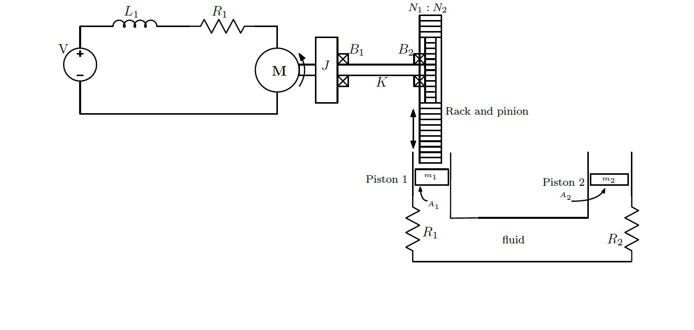
Expert Answer:
Instructions for Bond Graph Representation In order to develop a bond graph for a hydraulic system w... View the full answer

Related Book For 
Thermodynamics An Engineering Approach
ISBN: 978-0073398174
8th edition
Authors: Yunus A. Cengel, Michael A. Boles
Posted Date:
