

Consider the circuit in Figure P17.14. Neglect base currents. (a) What are the logic 1 and logic
Question:
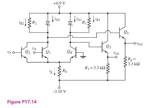
Consider the circuit in Figure P17.14. Neglect base currents.
(a) What are the logic 1 and logic 0 values at the output terminals \(v_{O 1}\) and \(v_{O 2}\) ?.
(b) For \(v_{X}=v_{Y}=\operatorname{logic} 0\), determine \(R_{E}\) such that \(i_{E}=0.25 \mathrm{~mA}\).
(c) Using the results of part (b), determine \(R_{1}\) such that \(i_{D 1}=2 i_{R 1}\) when \(Q_{R}\) is conducting.
(d) For \(v_{X}=v_{Y}=\) logic 1 and \(R_{1}=R_{2}\), determine \(i_{E}, i_{R 2}\), and \(i_{D 2}\).
(e) For \(v_{X}=\operatorname{logic} 0\) and \(v_{Y}=\operatorname{logic} 1\), calculate the power dissipation in the circuit.
Fantastic news! We've Found the answer you've been seeking!
Step by Step Answer:

Answered By
Brown Arianne
Detail-oriented professional tutor with a solid 10 years of experience instilling confidence in high school and college students. Dedicated to empowering all students with constructive feedback and practical test-taking strategies. Effective educator and team player whether working in a school, university, or private provider setting. Active listener committed to helping students overcome academic challenges to reach personal goals.
2+ Reviews
10+ Question Solved
Related Book For 

Microelectronics Circuit Analysis And Design
ISBN: 9780071289474
4th Edition
Authors: Donald A. Neamen
Question Posted:
