

For the TTL circuit in Figure P17.31, assume parameters of (beta_{F}=50), (beta_{R}=0.1, quad V_{B E}(mathrm{on})=0.7 mathrm{~V}, quad
Question:
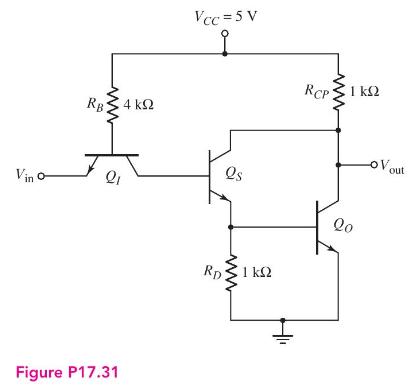
For the TTL circuit in Figure P17.31, assume parameters of \(\beta_{F}=50\), \(\beta_{R}=0.1, \quad V_{B E}(\mathrm{on})=0.7 \mathrm{~V}, \quad V_{B E}(\mathrm{sat})=0.8 \mathrm{~V}\), and \(V_{C E}(\mathrm{sat})=0.1 \mathrm{~V}\).
(a) Determine \(i_{R B}, i_{R C P}, i_{B o}\), and \(V_{\text {out }}\) for (i) \(V_{\text {in }}=0.1 \mathrm{~V}\) and (ii) \(V_{\text {in }}=5 \mathrm{~V}\).
(b) For the case when five similar type load circuits are connected to the output, calculate the power dissipated in the circuit shown for (i) \(V_{\text {in }}=0.1 \mathrm{~V}\) and (ii) \(V_{\text {in }}=5 \mathrm{~V}\).
Fantastic news! We've Found the answer you've been seeking!
Step by Step Answer:

Answered By
Muhammad Umair
I have done job as Embedded System Engineer for just four months but after it i have decided to open my own lab and to work on projects that i can launch my own product in market. I work on different softwares like Proteus, Mikroc to program Embedded Systems. My basic work is on Embedded Systems. I have skills in Autocad, Proteus, C++, C programming and i love to share these skills to other to enhance my knowledge too.
1+ Reviews
10+ Question Solved
Related Book For 

Microelectronics Circuit Analysis And Design
ISBN: 9780071289474
4th Edition
Authors: Donald A. Neamen
Question Posted:
