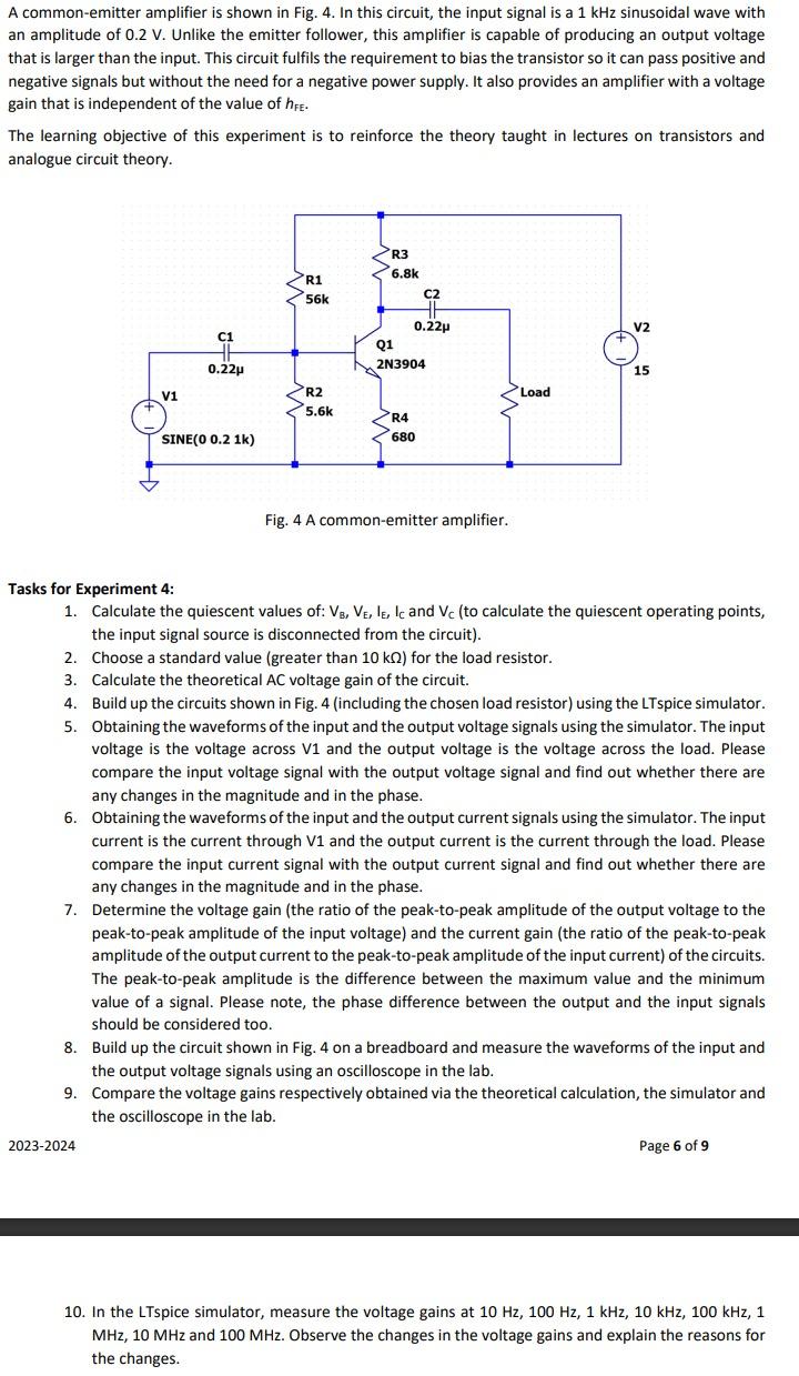
A common-emitter amplifier is shown in Fig. 4. In this circuit, the input signal is a...
Fantastic news! We've Found the answer you've been seeking!
Question:
Transcribed Image Text:
A common-emitter amplifier is shown in Fig. 4. In this circuit, the input signal is a 1 kHz sinusoidal wave with an amplitude of 0.2 V. Unlike the emitter follower, this amplifier is capable of producing an output voltage that is larger than the input. This circuit fulfils the requirement to bias the transistor so it can pass positive and negative signals but without the need for a negative power supply. It also provides an amplifier with a voltage gain that is independent of the value of hFE. The learning objective of this experiment is to reinforce the theory taught in lectures on transistors and analogue circuit theory. V1 C1 0.22μ SINE(0 0.2 1k) 2023-2024 R1 56k R2 5.6k R3 6.8k C2 0.22μ Q1 2N3904 R4 680 Fig. 4 A common-emitter amplifier. Load V2 15 Tasks for Experiment 4: 1. Calculate the quiescent values of: VB, VE, IE, IC and Vc (to calculate the quiescent operating points, the input signal source is disconnected from the circuit). 2. Choose a standard value (greater than 10 k) for the load resistor. 3. Calculate the theoretical AC voltage gain of the circuit. 4. Build up the circuits shown in Fig. 4 (including the chosen load resistor) using the LTspice simulator. 5. Obtaining the waveforms of the input and the output voltage signals using the simulator. The input voltage is the voltage across V1 and the output voltage is the voltage across the load. Please compare the input voltage signal with the output voltage signal and find out whether there are any changes in the magnitude and in the phase. 6. Obtaining the waveforms of the input and the output current signals using the simulator. The input current is the current through V1 and the output current is the current through the load. Please compare the input current signal with the output current signal and find out whether there are any changes in the magnitude and in the phase. 7. Determine the voltage gain (the ratio of the peak-to-peak amplitude of the output voltage to the peak-to-peak amplitude of the input voltage) and the current gain (the ratio of the peak-to-peak amplitude of the output current to the peak-to-peak amplitude of the input current) of the circuits. The peak-to-peak amplitude is the difference between the maximum value and the minimum value of a signal. Please note, the phase difference between the output and the input signals should be considered too. 8. Build up the circuit shown in Fig. 4 on a breadboard and measure the waveforms of the input and the output voltage signals using an oscilloscope in the lab. 9. Compare the voltage gains respectively obtained via the theoretical calculation, the simulator and the oscilloscope in the lab. Page 6 of 9 10. In the LTspice simulator, measure the voltage gains at 10 Hz, 100 Hz, 1 kHz, 10 kHz, 100 kHz, 1 MHz, 10 MHz and 100 MHz. Observe the changes in the voltage gains and explain the reasons for the changes. A common-emitter amplifier is shown in Fig. 4. In this circuit, the input signal is a 1 kHz sinusoidal wave with an amplitude of 0.2 V. Unlike the emitter follower, this amplifier is capable of producing an output voltage that is larger than the input. This circuit fulfils the requirement to bias the transistor so it can pass positive and negative signals but without the need for a negative power supply. It also provides an amplifier with a voltage gain that is independent of the value of hFE. The learning objective of this experiment is to reinforce the theory taught in lectures on transistors and analogue circuit theory. V1 C1 0.22μ SINE(0 0.2 1k) 2023-2024 R1 56k R2 5.6k R3 6.8k C2 0.22μ Q1 2N3904 R4 680 Fig. 4 A common-emitter amplifier. Load V2 15 Tasks for Experiment 4: 1. Calculate the quiescent values of: VB, VE, IE, IC and Vc (to calculate the quiescent operating points, the input signal source is disconnected from the circuit). 2. Choose a standard value (greater than 10 k) for the load resistor. 3. Calculate the theoretical AC voltage gain of the circuit. 4. Build up the circuits shown in Fig. 4 (including the chosen load resistor) using the LTspice simulator. 5. Obtaining the waveforms of the input and the output voltage signals using the simulator. The input voltage is the voltage across V1 and the output voltage is the voltage across the load. Please compare the input voltage signal with the output voltage signal and find out whether there are any changes in the magnitude and in the phase. 6. Obtaining the waveforms of the input and the output current signals using the simulator. The input current is the current through V1 and the output current is the current through the load. Please compare the input current signal with the output current signal and find out whether there are any changes in the magnitude and in the phase. 7. Determine the voltage gain (the ratio of the peak-to-peak amplitude of the output voltage to the peak-to-peak amplitude of the input voltage) and the current gain (the ratio of the peak-to-peak amplitude of the output current to the peak-to-peak amplitude of the input current) of the circuits. The peak-to-peak amplitude is the difference between the maximum value and the minimum value of a signal. Please note, the phase difference between the output and the input signals should be considered too. 8. Build up the circuit shown in Fig. 4 on a breadboard and measure the waveforms of the input and the output voltage signals using an oscilloscope in the lab. 9. Compare the voltage gains respectively obtained via the theoretical calculation, the simulator and the oscilloscope in the lab. Page 6 of 9 10. In the LTspice simulator, measure the voltage gains at 10 Hz, 100 Hz, 1 kHz, 10 kHz, 100 kHz, 1 MHz, 10 MHz and 100 MHz. Observe the changes in the voltage gains and explain the reasons for the changes.
Expert Answer:
Answer rating: 100% (QA)
Task 1 Calculate the quiescent values of the circuit components To calculate the quiescent values of the circuit components we need to disconnect the ... View the full answer
Related Book For
Analysis and Design of Analog Integrated Circuits
ISBN: 978-0470245996
5th edition
Authors: Paul R. Gray, ? Paul J. Hurst Stephen H. Lewis, ? Robert G. Meyer
Posted Date:
Students also viewed these finance questions
-
(1 point) Find an antiderivative of q(t) = (1+4) Q(t)=
-
For this exercise, if you have chosen a real organization as the model for your hypothetical organization, please give your organization a new, hypothetical name, and create original wording for the...
-
A variable-gain CMOS amplifier is shown in Fig. 8.52. Note that M 4 represents shunt feedback around M 6 . Assuming that the bias value of V i is adjusted so that V GD6 = 0 V dc, calculate bias...
-
An extruder has a barrel diameter of 100 mm. The screw rotates at 100 rpm, has a channel depth of 6 mm, and a flight angle of 17.5. What is the highest flow rate of polypropylene that can be achieved?
-
a. A vacant lot acquired for $50,000 is sold for $130,000 in cash. What is the effect of the sale on the total amount of the sellers? (1) Assets, (2) Liabilities, (3) Owners equity? b. Assume that...
-
\(\sim p ightarrow q \leftrightarrow r\) For each of the following compound logical statement, apply the proper dominance of connectives by adding parentheses to indicate the order in which the...
-
You have been assigned to the first audit of the Chicago Company for the year ending March 31, 2011. Accounts receivable were confirmed on December 31, 2010, and at that date the receivables...
-
Indigo Inc. issued $3,975,000 of convertible 5-year bonds on July 1, 2020. The bonds provide for 6% interest payable semiannually on January 1 and July 1. The discount in connection with the issue...
-
A block on a frictionless table is connected as shown in FIGURE P15.75 to two springs having spring constants k 1 and k 2 . Find an expression for the blocks oscillation frequency f in terms of the...
-
S %24%2F2X5877001013 S20532475 P700101317300000OOOO.COIX.SX2458P700 00000000000000 + - P3.45A Analyze Manufacturing Overhead (Learning Objectives 3 & 5) Hartley Uniforms Produces Uniforms. The...
-
What is the purpose of accounting in business? 2.How does inventory asset and cost flows of a merchandising company? 3.What are the financial statements companies prepare,and include the purpose...
-
Differentiate Differentiate the function. 5+3) y= (5x4 x+4) (-x + 3) y' =
-
Explain how a change in product (sales) mix to a higher proportion in export sales could result in a lower level of net income.
-
Priya is an artist who creates original artworks depicting Sydney Harbour and its environs. She then prints fifty posters from each of the works and sells them from her stall in the Rocks Markets on...
-
Tanshoura Inc. previously accounts its cost using only direct materials and direct labor. This year they want to know what should from part of their factory overhead. Raw materials purchased $23,340...
-
Case Name (Who is suing who?): Case Issues explained: Reasoning (explain the legal issues as they relate to the facts of this scenario): Risk Reduction (common sense - what should the parties have...
-
Briefly describe the following types of group life insurance plans: a. Group term life insurance b. Group accidental death and dismemberment insurance (AD&D) c. Group universal life insurance d....
-
Determine the input resistance, transconductance, and output resistance of the CE amplifier of Fig. 3.7 if R C = 20 k and I C = 250μ A. Assume that r b = 0. Figure 3.7 VDD = 5 V V; Vo...
-
Use half-circuit analysis to determine A dm , A cm , A cmdm , and A dmcm for a resistively loaded differential pair with mismatched resistive loads, R 1 and R 2 . Assume that R 1 = 10.1 k and R 2 =...
-
In the circuit of Fig. 6.55, determine the cor-rect value ofRxso that the output voltage is zero when the input voltage is zero. Assume a nonzero input bias current, but zero input offset current and...
-
Calculate \(\frac{38}{73}+\frac{7}{73}\).
-
Calculate \(\frac{4}{9}+\frac{7}{12}\).
-
Convert 17.03347 to fraction form.
Study smarter with the SolutionInn App