

(a) Design a four-resistor bias network with the configuration shown in Figure P5.77 such that the (Q)-point...
Question:
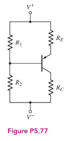
(a) Design a four-resistor bias network with the configuration shown in Figure P5.77 such that the \(Q\)-point values are \(I_{C Q}=1.2 \mathrm{~mA}\) and \(V_{E C Q}=6 \mathrm{~V}\). The bias voltages are \(V^{+}=9 \mathrm{~V}\) and \(V^{-}=-9 \mathrm{~V}\). A transistor with \(\beta=75\) is available. The voltage across the emitter resistor should be approximately 1.5V.
(b) Replace the designed resistors in part (a) with standard resistors with values closest to the designed values. Determine the resulting \(Q\)-point.
Fantastic news! We've Found the answer you've been seeking!
Step by Step Answer:

Answered By
Jinah Patricia Padilla
Had an experience as an external auditor in Ernst & Young Philippines and currently a Corporate Accountant in a consultancy company providing manpower to a 5-star hotel in Makati, Philippines, Makati Diamond Residences
120+ Reviews
150+ Question Solved
Related Book For 

Microelectronics Circuit Analysis And Design
ISBN: 9780071289474
4th Edition
Authors: Donald A. Neamen
Question Posted:
