

Figure P17.23 shows an improved version of the DTL circuit. One offset diode is replaced by transistor
Question:
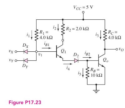
Figure P17.23 shows an improved version of the DTL circuit. One offset diode is replaced by transistor \(Q_{1}\), providing increased current drive to \(Q_{o}\). Assume \(\beta=20\) for both transistors.
(a) For \(v_{X}=v_{Y}=5 \mathrm{~V}\), determine the currents and voltages listed in the figure.
(b) Calculate the maximum fanout for the low output condition.
Fantastic news! We've Found the answer you've been seeking!
Step by Step Answer:

Answered By
Kirti Kaushal
Having experience of more than 10 years is good enough to coach my students. Currently, I am working as an active supervisor of ACCA students. In my career, I helped students in financial accounting, management accounting, cost accounting, financial reporting, taxation, and audit. I also helped students publish their articles or papers in good journals. I also helped students with thesis and objective writing.
1+ Reviews
10+ Question Solved
Related Book For 

Microelectronics Circuit Analysis And Design
ISBN: 9780071289474
4th Edition
Authors: Donald A. Neamen
Question Posted:
