

Question: An electro-hydraulic positioning system is shown in Figure P11.38. Use the following values. K a = 10 V/A Ki = 10 2 in./V K 2
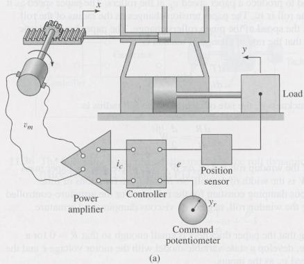
An electro-hydraulic positioning system is shown in Figure P11.38. Use the following values.
Ka = 10 V/A Ki = 10–2 in./V
K2 = 3 × 10⁵ sec–3 K3 = 20 V/in.
z = 0.8 wn = 100 rad/sec t = 0.01 sec
a. Develop a state-variable model of the plant with the controller current ic as the input and the displacement y as the output.
b. Assuming that proportional control is used so that Gc(s) = Kp, develop a state model of the system with \y as the input and y as the output. Draw the root locus and use it to determine whether or not the system can be made stable with an appropriate choice for the value of KP.
Figure P11.38
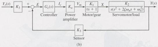
Load DR Position sensor Power Controller amplifier Command potentiometer Y,(s) K7Ys) K. Ge(s) Ka ControllerPowerMotor/ge ervomotor/load amplifier Sensor
Step by Step Solution
3.41 Rating (160 Votes )
There are 3 Steps involved in it
a For P I control with 1 For modified I control b For a unitst... View full answer

Get step-by-step solutions from verified subject matter experts
Document Format (1 attachment)
755-C-D-S-D (669).docx
120 KBs Word File