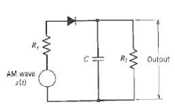
Figure shows the circuit diagram of an envelope detector. It consists simply of a diode and resistor-capacitor
Question:
Figure shows the circuit diagram of an envelope detector. It consists simply of a diode and resistor-capacitor (RC) filter. On a positive half-cycle of the input signal, the diode is forward-biased and the capacitor C charges up rapidly to the peak value of the input signal. When the input signal falls below this value, the diode becomes reverse-biased and the capacitor C discharges slowly through the load resistor Rl. The discharging process continuous until the next positive half-cycle, therefore, the charging-discharging routine is continued.
(a) Specify the condition that must be satisfied by the capacitor C for it to charge rapidly and thereby follow the input voltage up to the positive peak when the diode is conducting.
(b) Specify the condition which the load resistor R1 must satisfy so that the capacitor C discharge slowly between positive peaks of the carrier wave, but not so long that the capacitor voltage will not discharge at the maximum rate of changes of the modulatingwave.

Step by Step Answer:


