

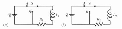
Question: In Figure a, switch S has been closed on A long enough to establish a steady current in the inductor of inductance L1 = 5.00
In Figure a, switch S has been closed on A long enough to establish a steady current in the inductor of inductance L1 = 5.00 mH and the resistor of resistance R1 = 25.0??. Similarly, in Figure b, switch S has been closed on A long enough to establish a steady current in the inductor of inductance L2 = 3.00 mH and the resistor of resistance R2 = 30.0??. The ratio ф02/ф01 of the magnetic flux through a turn in inductor 2 to that in inductor 1 is 1.50. At time t = 0, the two switches are closed on B. At what time r is the flux through a turn in the two inductors equal?
AS AS B9 (b) (a)
Step by Step Solution
3.39 Rating (171 Votes )
There are 3 Steps involved in it
Because of the decay of current Eq 3045 that occurs after ... View full answer

Get step-by-step solutions from verified subject matter experts
Document Format (1 attachment)
2-P-E-I (270).docx
120 KBs Word File