

Question: (a) Neglecting capacitive effects, calculate the noise figure in decibels of the circuit of Fig. 11.52 with R S = 5 kΩ. Use data as
(a) Neglecting capacitive effects, calculate the noise figure in decibels of the circuit of Fig. 11.52 with RS= 5 kΩ. Use data as in Problem 11.10.
(b) If the flicker noise corner frequency for each device is 1 kHz, calculate the low frequency where the spot noise figure is 3 dB above the value in (a).
Data from Prob. 11.10:
The ac schematic of a low-input-impedance common-base amplifier is shown in Fig. 11.52.
(a) Calculate the equivalent noise voltage and current generators of this circuit at the emitter of Q1 using IC1 = IC2 = 1 mA, rb1 = rb2 = 0, β1 = β2 = 100, fT1 = fT2 = 400 MHz. Neglect flicker noise but include capacitive effects in the transistors. Use SPICE to check your result.
(b) If RS = 5 kΩ, and later stages limit the bandwidth to a sharp cutoff at 150 MHz, calculate the value of iS giving an output signal-to-noise ratio of 10 dB.
Fig. 11.52:
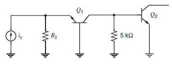
Q2 5 k2 Rs
Step by Step Solution
3.54 Rating (178 Votes )
There are 3 Steps involved in it
a From 1110 the total input noise current is 64 10 24 3... View full answer

Get step-by-step solutions from verified subject matter experts
Document Format (2 attachments)
1528_605d88e1c1f71_687030.pdf
180 KBs PDF File
1528_605d88e1c1f71_687030.docx
120 KBs Word File