

Question: The ac schematic of a shunt-series feedback amplifier is shown in Fig. 8.31. Element values are R F = 1 kΩ, R E = 100
The ac schematic of a shunt-series feedback amplifier is shown in Fig. 8.31. Element values are RF= 1 kΩ, RE= 100 Ω, RL1= 4 kΩ, RS= 1/yS= 1 kΩ, and zL= 0. Device data: β = 200, rb= 0, IC1= IC2= 1 mA, VA= 100 V.
(a) Calculate the overall gain io/ii, the loop transmission, and the input and output impedances at low frequencies.
(b) If the value of RL1 changes by +10 percent, what is the approximate change in overall transmission and input impedance?
Fig. 8.31:
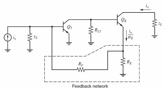
Q2 Z1. i, a2 Ys is RE Rf Feedback network
Step by Step Solution
3.55 Rating (148 Votes )
There are 3 Steps involved in it
a Basic amplifier Basic amplifier gain R 1 4k r 2 1g m2 R B r o1 330 K a 516 r ia 1 K ... View full answer

Get step-by-step solutions from verified subject matter experts
Document Format (2 attachments)
1528_605d88e1c9b06_687114.pdf
180 KBs PDF File
1528_605d88e1c9b06_687114.docx
120 KBs Word File