Consider Example 17.5, where a mixture of CO and methanol is being separated in a jacketed flash
Question:
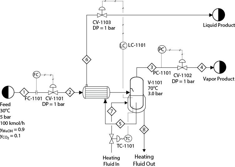
Consider Example 17.5, where a mixture of CO and methanol is being separated in a jacketed flash vessel. The heat content in the bottom product from the flash vessel is now recovered in heat exchanger E-1103, as shown in Figure P17.8. Note the difference in the inlet feed pressure compared to Example 17.5, which is included to take care of the pressure drop in the exchanger, E-1103. Also note the changed location of the control valve, CV-1103, used for level control of V-1102. The remainder of the specifications are the same as in Example 17.5. For this problem do the following:
Figure P17.8
1. Develop a “rigorous” design of the heat exchanger, E-1103, considering a maximum pressure drop of 0.1 bar in the shell and tube sides and a minimum temperature approach of 15°C.
2. Tune the four controllers, FC-1101, TC-1101, PC-1101, and LC-1101, by using both of the methods mentioned in Chapter 17 (i.e., by using stability margins and by using an approximate process model) and applying various rules similar to those used in Example 17.5. Did the tuning parametesrs differ from the ones in Example 17.5? If they did differ, explain why.
3. Step decrease the feed flow to 40 kmol/h. Show the differences in the transient response in the level controller with the controllers being tuned by different rules.
4. Use the tuning parameters for which you obtained the “best” performance in Part (c). The process is again at set at steady state with 100 kmol/h feed flowrate. Keep increasing the proportional gain of the level controller, LC- 1101, each time by 30% up to 150% of the original gain. For each value of the proportional gain, step decrease the feed flow from 100 kmol/h to 40 kmol/h. Even though the tuning of the temperature controller, TC-1101, was not altered, did you notice any change in its performance? Why does this happen? Take corrective action such that the performance of the TC is similar to what it was before.
Example 17.5
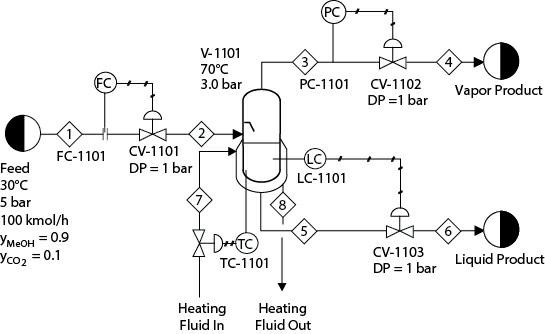
Consider Example 17.3, where a mixture of CO and methanol is separated in a jacketed flash vessel. The inlet temperature of the heating medium is 90°C, and its specific heat is similar to that of water. There is no phase change of the heating medium in the jacket. The heat transfer option in the dynamic simulation is “LMTD,” and the heating-medium flowrate is manipulated to maintain the vessel outlet temperature at 70°C, as shown in Figure E17.5(a). Figure E17.5(a) also shows that the flow dynamics of the heating medium are neglected, assuming perfect control. So there are four controllers: FC-1101, PC-1101, LC-1101, and TC-1101. Tune these controllers by using both methods mentioned before (i.e., by using stability margins and by using an approximate process model) and by applying the various rules discussed previously. Then decrease the feed flow to 50 kmol/h in a single step. Show the differences in the transient response of the outlet temperature with the controllers being tuned by different rules.
Figure E17.5
Step by Step Answer:

Analysis Synthesis And Design Of Chemical Processes
ISBN: 9780134177403
5th Edition
Authors: Richard Turton, Joseph Shaeiwitz, Debangsu Bhattacharyya, Wallace Whiting


