Modify the preceding problem to develop a flowsheet as shown in Figure P16.16. Replace the heat exchanger,
Question:
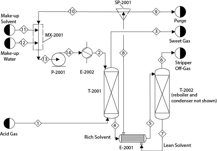
Modify the preceding problem to develop a flowsheet as shown in Figure P16.16. Replace the heat exchanger, E-2001, with a countercurrent heat exchanger between the feed to and product from the stripper. Assume that about 0.5% of the solvent circulation rate is purged from SP-2001. The purging (and other methods such as thermal reclaiming, mechanical filtration, washing of the solvent, etc.) helps to reduce the buildup of undesired contaminants in the system. Stream 11, makeup MDEA, and Stream 12, makeup water, are pure. The discharge pressure of P- 2001 is 2.6 atm. The solvent is cooled to 38°C in E-2002 and sent to T-2001. You can manipulate the temperature specifications in E-2001, satisfying a minimum temperature approach of about 10°C. Implement two calculator blocks. One calculator block calculates the flowrate of Stream 11 based on the solvent loss. Another calculator block calculates the water makeup to maintain the water concentration in Stream 13 at 66.6 mol%. Note that this water concentration is much different compared to what was considered in Problem 13.29. Finally, this system will have one design block, two calculator blocks, and a recycle stream.
Figure P16.16
Did you face any convergence problems?
Problem 13.29
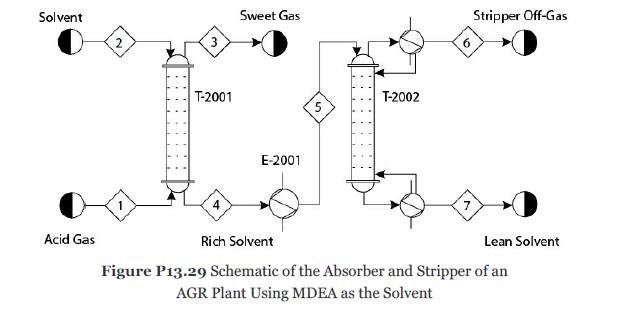
Consider Problem 13.28. The solvent MDEA becomes rich in acid gases. To recycle this solvent, it is first heated to 90°C in exchanger E-2001 and then sent to the top stage of the stripper T-2002 as shown in Figure P13.29. Develop a nonequilibrium-stage model of the stripper with 20 theoretical stages, a partial-vapor condenser, and a kettletype reboiler. Reflux ratio (mole basis) = 0.7 and bottoms/feed ratio (mole basis) = 0.97. The pressure in the condenser is 1.4 atm, and the pressure drop through the entire column should be calculated. Consider the ionic reactions in all the stages, including the condenser and reboiler. It can be assumed that all ionic reactions reach equilibrium in the condenser and reboiler because of the longer residence times. Assume that the tray hardware is similar to the absorber. The mass transfer and the ionic reactions in the liquid and vapor films can be modeled similarly to Problem 13.28. For this problem determine the following:
1. What are the duties of the stripper and reboiler?
2. What are the compositions of Streams 6 and 7?
3. What operating condition(s) of the stripper would you change if you wanted to increase the purity of Stream 7?
Step by Step Answer:

Analysis Synthesis And Design Of Chemical Processes
ISBN: 9780134177403
5th Edition
Authors: Richard Turton, Joseph Shaeiwitz, Debangsu Bhattacharyya, Wallace Whiting


