

Question: Given the following logic diagram for an accumulator, write down the Verilog module implementation of it. Assume a positive edgetriggered register and asynchronous Rst. In
Given the following logic diagram for an accumulator, write down the Verilog module implementation of it. Assume a positive edgetriggered register and asynchronous Rst.
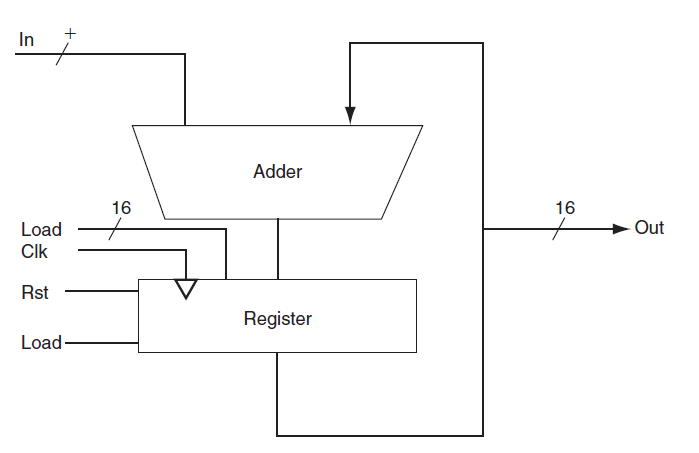
In Adder 16 16 Out Load Clk Rst Register Load
Step by Step Solution
★★★★★
3.29 Rating (178 Votes )
There are 3 Steps involved in it
1 Expert Approved Answer
Step: 1 Unlock

module ACCClk Rst Load IN LOAD OUT input Clk Rst Load input 30 ... View full answer
Question Has Been Solved by an Expert!
Get step-by-step solutions from verified subject matter experts
Step: 2 Unlock
Step: 3 Unlock