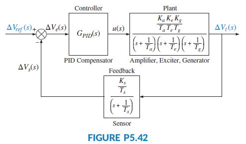
Figure P5.42 Shows the block diagram of an Automatic Voltage Regulator (Gozde, 2011). Assume in this diagram
Question:
Figure P5.42 Shows the block diagram of an Automatic Voltage Regulator (Gozde, 2011). Assume in this diagram the following parameter values: Ka = 10, Ta = 0.1,Ke = 1, Te = 0.4, Kg = 1, Tg = 1, Ks = 1, and Ts = 0.001. Also assume that the PID transfer function is substituted by a simple integrator, namely GPID(s) = K/s. Find the range of K for which the system is closed-loop stable.

Fantastic news! We've Found the answer you've been seeking!
Step by Step Answer:
Related Book For 

Question Posted:


