

Question: The measurement bandwidth was increased so that the first three modes were captured. Again, the direct, (X_{1} / F_{1}), and cross FRFs, (X_{2} / F_{1})
The measurement bandwidth was increased so that the first three modes were captured. Again, the direct, \(X_{1} / F_{1}\), and cross FRFs, \(X_{2} / F_{1}\) through \(X_{5} / F_{1}\), were measured. The imaginary part of the direct FRF for the entire bandwidth is shown in Fig. P6.6a. The three natural frequencies are 200, 550, and 1,250 Hz.
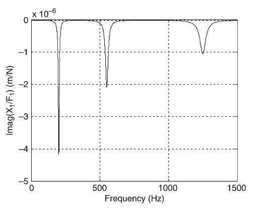
Fig. P6.6a Direct FRF \(X_{1} / F_{1}\).
Use Figs. P6.6b through P6.6f to identify the mode shape that corresponds to the \(1,250 \mathrm{~Hz}\) natural frequency. Plot your results using the same approach described.
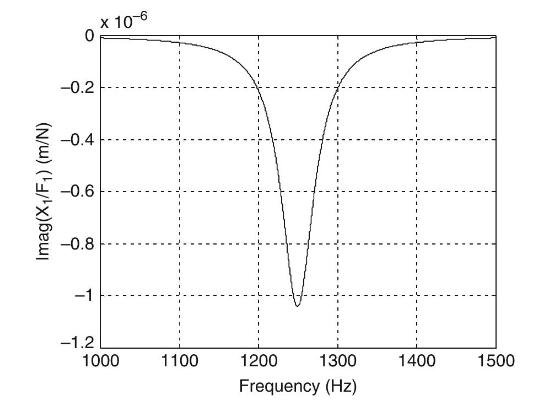
Fig. P6.6b Direct \(\mathrm{FRF} X_{1} / F_{1}\) (mode 3 only).
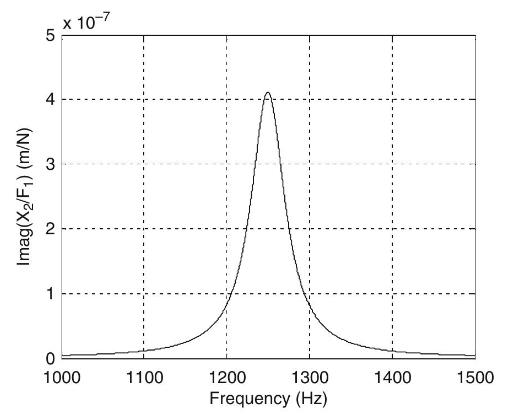
Fig. P6.6c Cross FRF \(X_{2} / F_{1}\).
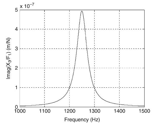
Fig. P6.6d Cross FRF \(X_{3} / F_{1}\).
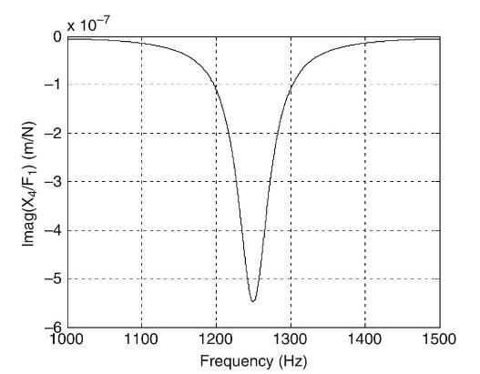
Fig. P6.6e Cross FRF \(X_{4} / F_{1}\).
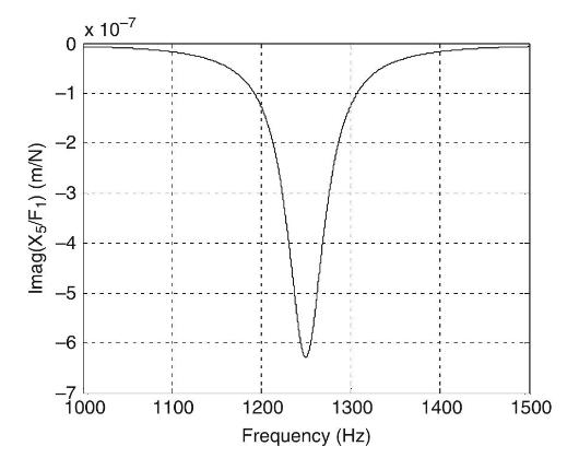
Fig. P6.6f Cross FRF \(X_{5} / F_{1}\).
Imag(X/F) (m/N) -1 -2 10-6 -5 500 1000 1500 Frequency (Hz)
Step by Step Solution
3.38 Rating (154 Votes )
There are 3 Steps involved in it

Get step-by-step solutions from verified subject matter experts