

Question: AP3.1 Consider the electromagnetic suspension system shown in Figure AP3.1. An electromagnet is located at the upper part of the experimental system. Using the electromagnetic
AP3.1 Consider the electromagnetic suspension system shown in Figure AP3.1. An electromagnet is located at the upper part of the experimental system. Using the electromagnetic force
f, we want to suspend the iron ball. Note that this simple electromagnetic suspension system is essentially unworkable. Hence feedback control is indispensable. As a gap sensor, a standard induction probe of the type of eddy current is placed below the ball [20].
Assume that the state variables are x1 (t) = x(t), x2 (t) = x(t), and x3 (t) = i(t). The electromagnet has an inductance L = 0.508 H and a resistance R = 23.2 . Use a Taylor series approximation for the electromagnetic force. The current is i1 (t) = I0 + i(t), where I0 = 1.06 A is the operating point and i(t)
is the variable. The mass m is equal to 1.75 kg. The gap is xg (t) = X0 + x(t), where X0 = 4.36 mm is the operating point and x(t) is the variable. The electromagnetic force is f (t) = k(i1 (t)/xg (t)) , 2 where k = 2.9×10⁻⁴ N m2/A2 . Determine the matrix differential equation and the equivalent transfer function X(s)/V(s).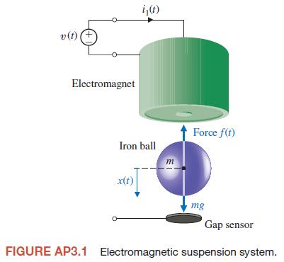
v(t) (+ i(t) Electromagnet Iron ball x(t) m Force f(t) mg Gap sensor FIGURE AP3.1 Electromagnetic suspension system.
Step by Step Solution
There are 3 Steps involved in it

Get step-by-step solutions from verified subject matter experts