

Question: P6.7 The linear model of a phase detector (phase-lock loop) can be represented by Figure P6.7 [9]. The phase-lock systems are designed to maintain zero
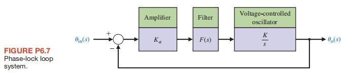
P6.7 The linear model of a phase detector (phase-lock loop) can be represented by Figure P6.7 [9]. The phase-lock systems are designed to maintain zero dif
ference in phase between the input carrier signal and a local voltage-controlled oscillator. The filter for a particular application is chosen as
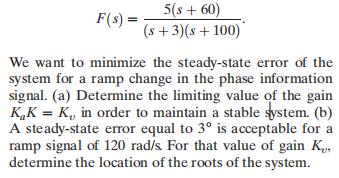
F(s) = 5(s+60) (s+3)(s +100) We want to minimize the steady-state error of the system for a ramp change in the phase information signal. (a) Determine the limiting value of the gain KK = K,, in order to maintain a stable system. (b) A steady-state error equal to 3 is acceptable for a ramp signal of 120 rad/s. For that value of gain K, determine the location of the roots of the system.
Step by Step Solution
There are 3 Steps involved in it

Get step-by-step solutions from verified subject matter experts