

Question: P7.7 The speed control system for an isolated power system is shown in Figure P7.7. The valve controls the steam flow input to the turbine
P7.7 The speed control system for an isolated power system is shown in Figure P7.7. The valve controls the steam flow input to the turbine in order to account for load changes ∆L s( ) within the power distribu
tion network. The equilibrium speed desired results in a generator frequency equal to 60 cps. The effec
tive rotary inertia J is equal to 4000 and the friction constant b is equal to 0.75. The steady-state speed regulation factor R is represented by the equation
R L ≈ − ( ) ω ω 0 r , /∆ where ωr equals the speed at rated load and ω0 equals the speed at no load. We want to obtain a very small R, usually less than 0.10.
(a) Using root locus techniques, determine the regula
tion R attainable when the damping ratio of the roots of the system must be greater than 0.60.
(b) Verify that the steady-state speed deviation for a load torque change ∆ = L s( ) ∆ /L s is, in fact, approximately equal to R L∆ when R ≤ 0.1. 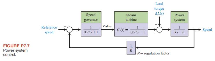
FIGURE P7.7 Power system control. Load torque Speed Steam AL(s) Power governor turbine system Reference 1 Valve speed 0.25s +1 G(s)= Speed 0.25s +1 Js+b R regulation factor =
Step by Step Solution
There are 3 Steps involved in it

Get step-by-step solutions from verified subject matter experts