

Question: P8.10 A linear actuator is used in the system shown in Figure P8.10 to position a mass M . The actual posi tion of the
P8.10 A linear actuator is used in the system shown in Figure P8.10 to position a mass M. The actual posi
tion of the mass is measured by a slide wire resistor, and thus H s( ) = 1.0. The amplifier gain is selected so that the steady-state error of the system is less than 1% of the magnitude of the position reference
R s( ). The actuator has a field coil with a resistance
Rf = Ω 0.1 and Lf = 0.2 H. The mass of the load is
M = 0.1 kg, and the friction is b = 0.2 N s m. The spring constant is k = 0.4 N m.
(a) Determine the gain K necessary to maintain a steady-state error for a step input less than 1%.
(b) Sketch the Bode plot of the loop transfer function.
(c) Sketch the Bode plot for the closed-loop transfer function. Determine
Mp r ω, ω , and the bandwidth.
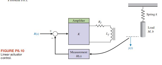
FIGURE P8.10 Linear actuator control. Amplifier Rf R(s) K Measurement H(s) y(1) www Spring k Load M, b
Step by Step Solution
There are 3 Steps involved in it

Get step-by-step solutions from verified subject matter experts