

Question: P2.35 A feedback control system has the structure shown in Figure P2.35. Determine the closed-loop transfer function Y1s2/R1s2 (a) by block diagram manipulation and (b)
P2.35 A feedback control system has the structure shown in Figure P2.35. Determine the closed-loop transfer function Y1s2/R1s2
(a) by block diagram manipulation and
(b) by using a signal-flow graph and Mason’s signal-flow gain formula.
(c) Select the gains K1 and K2 so that the closed-loop response to a step input is critically damped with two equal roots at s = -10.
(d) Plot the critically damped response for a unit step input. What is the time required for the step response to reach 90% of its final value?
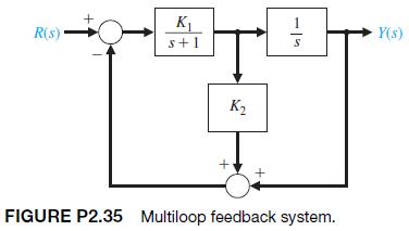
R(S)- K s+1 K + 1 57 FIGURE P2.35 Multiloop feedback system. Y(s)
Step by Step Solution
There are 3 Steps involved in it

Get step-by-step solutions from verified subject matter experts