

The digital controller in Figure P7.2 has three outputs, X, Y, and Z, and two inputs, A
Question:
The digital controller in Figure P7.2 has three outputs, X, Y, and Z, and two inputs, A and B. It is externally driven by a clock. The controller is continuously going through the following sequence of events: At the beginning of the first clock cycle, line X is set to 1. At the beginning of the second clock cycle, either line Y or Z is set to 1, depending on whether line A was equal to 1 or 0, respectively, in the previous clock cycle. The con- troller then waits until line B is set to 1. On the following positive edge of the clock, the controller sets output Z to 1 for the duration of one clock cycle, then resets all output sig- nals to 0 for one clock cycle. The sequence is repeated, starting at the next positive edge of the clock. Draw a state diagram and give a suitable logic design for this controller.LO1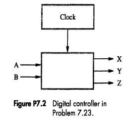
Step by Step Answer:

This question has not been answered yet.
You can Ask your question!


Computer Organization
ISBN: 9780072320862
5th Edition
Authors: V Carl Hamacher, Carl Hamacher, Zvonko G Vranesic, Safwat G Zaky
