

Question: For the liquid storage system shown in Fig. E15.4, the control objective is to regulate liquid level h 2 despite disturbances in ow rates, q
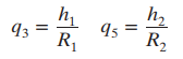
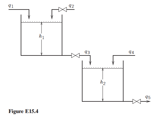
For the liquid storage system shown in Fig. E15.4, the control objective is to regulate liquid level h2 despite disturbances in flow rates, q1 and q4. Flow rate q2 can be manipulated. The two hand valves have the following flow head relations:
Do the following, assuming that the flow transmitters and the control valve have negligible dynamics. Also assume that the objective is tight level control.
(a) Draw a block diagram for a feedforward control system for the case where q4 can be measured and variations in q1 are neglected.
(b) Design a feedforward control law for case (a) based on a steady-state design (Eq. 15-40)
(c) Repeat part (b), but consider dynamic behavior.
(d) Repeat parts (a) through (c) for the situation where q1 can be measured and variations in q4 are neglected.
Step by Step Solution
There are 3 Steps involved in it

Get step-by-step solutions from verified subject matter experts