Question
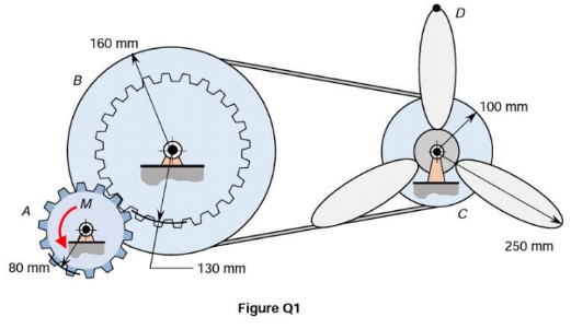
Shows the system used to spin the fan blades. The solid properties of each part or component are shown in Table Q1 Counter clockwise moment
Shows the system used to spin the fan blades. The solid properties of each part or component are shown in Table Q1

Counter clockwise moment M of magnitude 10 N.m is applied to gear A which is initially at est.
Draw the fee-body diagrams of gear A , gear pulley B and the combined pulley C and fan blades.
State all relevant assumptions required in kinematics and kinetics analysis of the system
Evaluate:
The time taken for the angular velocity of the fan blades to reach 1500 rpm the tension in the belt.
The acceleration of point D at the instant when the fan blades reach 1500 rmp.

Part Gear A Geared pulley B Combined pulley C and the fan blades Mass (kg) 2.0 5.0 2.5 Radius of gyration (mm) 60 120 110 80 mm B 160 mm M HO 130 mm Figure Q1 O C 100 mm 250 mm
Step by Step Solution
3.51 Rating (161 Votes )
There are 3 Steps involved in it
Step: 1
Consider Gear A ...
Get Instant Access to Expert-Tailored Solutions
See step-by-step solutions with expert insights and AI powered tools for academic success
Step: 2

Step: 3

Document Format ( 2 attachments)
608fb23b8c7f8_21223.pdf
180 KBs PDF File
608fb23b8c7f8_21223.docx
120 KBs Word File
Ace Your Homework with AI
Get the answers you need in no time with our AI-driven, step-by-step assistance
Get Started


