

Question
The pulley in the figure (Figure 1) represents different pulleys that are attached with outer radius and inner radius indicated in the table. The horizontal
The pulley in the figure (Figure 1) represents different pulleys that are attached with outer radius and inner radius indicated in the table. The horizontal rope is pulled to the right at a constant linear speed that is the same in each case, and none of the two separate ropes slips in its contact with the pulley.
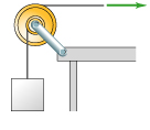
A). R_outer = 0.8m R_inner = 0.4m B). R_outer = 0.2m R_inner = 0.1m C). R_outer = 0.6m R_inner = 0.5m D). R_outer = 0.4m R_inner = 0.2m E). R_outer = 0.4m R_inner = 0.3m F). R_outer = 0.6m R_inner = 0.2m
Part A
Rank these scenarios on the basis of the linear speed of the block. Several points on the pulley are indicated in the figure. (Figure 2) Each letter designates a point on either the pulley or one of the two ropes. The horizontal rope is pulled to the right at a constant linear speed, and neither rope slips in its contact with the pulley.
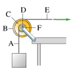
PART B Rank the designated points on the basis of their linear or tangential speed.
D -F B- A-
Step by Step Solution
3.37 Rating (144 Votes )
There are 3 Steps involved in it
Step: 1
A The expression for the linear speed of the block is given below Rearrange the above expression for the angular speed of the inner radius as follows ...
Get Instant Access to Expert-Tailored Solutions
See step-by-step solutions with expert insights and AI powered tools for academic success
Step: 2

Step: 3
Ace Your Homework with AI
Get the answers you need in no time with our AI-driven, step-by-step assistance
Get Started
Vector Mechanics for Engineers Statics and Dynamics
Authors: Ferdinand Beer, E. Russell Johnston, Jr., Elliot Eisenberg, William Clausen, David Mazurek, Phillip Cornwell
8th Edition
73212229, 978-0073212227