Answered step by step
Verified Expert Solution
Question
1 Approved Answer
1 10 service password-encryption). Disable the DNS lookup process (Hint: use the command no ip domain-lookup). You must complete the settings based on following
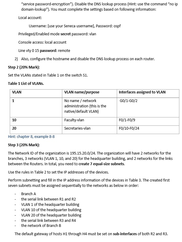
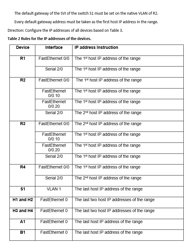
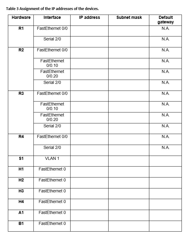
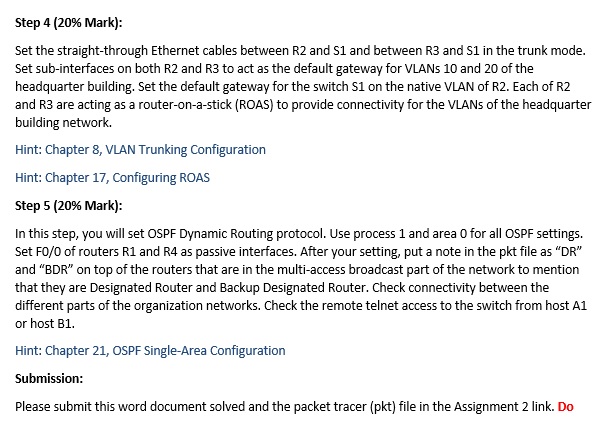
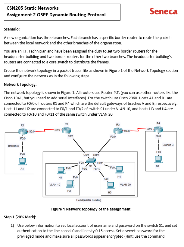
1 10 "service password-encryption"). Disable the DNS lookup process (Hint: use the command "no ip domain-lookup"). You must complete the settings based on following information: Local account: Console access: local account Line vty 0 15 password: remote 2) Also, configure the hostname and disable the DNS lookup process on each router. Step 2 (20% Mark): Set the VLANs stated in Table 1 on the switch S1. Table 1 List of VLANS. VLAN 20 Username: [use your Seneca username], Password: ospf Privileged/Enabled mode secret password: vlan VLAN name/purpose No name / network administration (this is the native/default VLAN) Faculty-vlan Secretaries-vlan Interfaces assigned to VLAN GO/1-GO/2 FO/1-F0/9 FO/10-FO/24 Hint: chapter 8, example 8-8 Step 3 (20% Mark): The Network ID of the organization is 195.15.20.0/24. The organization will have 2 networks for the branches, 3 networks (VLAN 1, 10, and 20) for the headquarter building, and 2 networks for the links between the Routers. In total, you need to create 7 equal-size subnets. Use the rules in Table 2 to set the IP addresses of the devices. Perform subnetting and fill in the IP address information of the devices in Table 3. The created first seven subnets must be assigned sequentially to the networks as below in order: Branch A the serial link between R1 and R2 VLAN 1 of the headquarter building VLAN 10 of the headquarter building VLAN 20 of the headquarter building the serial link between R3 and R4 the network of Branch B The default gateway of hosts H1 through H4 must be set on sub-interfaces of both R2 and R3. The default gateway of the SVI of the switch S1 must be set on the native VLAN of R2. Every default gateway address must be taken as the first host IP address in the range. Direction: Configure the IP addresses of all devices based on Table 3. Table 2 Rules for the IP addresses of the devices. Device Interface R1 R2 R3 R4 S1 H1 and H2 H3 and H4 A1 B1 FastEthernet 0/0 The 1st host IP address of the range Serial 2/0 The 1st host IP address of the range The 1st host IP address of the range The 1sthost IP address of the range The 1st host IP address of the range The 2nd host IP address of the range The 2nd host IP address of the range The 1st host IP address of the range The 1st host IP address of the range The 1st host IP address of the range FastEthernet 0/0 The 1st host IP address of the range The 2nd host IP address of the range The last host IP address of the range The last two host IP addresses of the range The last two host IP addresses of the range The last host IP address of the range The last host IP address of the range FastEthernet 0/0 FastEthernet 0/0.10 FastEthernet 0/0.20 Serial 2/0 FastEthernet 0/0 FastEthernet 0/0.10 FastEthernet 0/0.20 Serial 2/0 Serial 2/0 VLAN 1 FastEthernet 0 FastEthernet 0 FastEthernet 0 IP address Instruction FastEthernet 0 Table 3 Assignment of the IP addresses of the devices. Hardware Interface IP address R1 R2 R3 R4 S1 H1 H2 H3 H4 A1 B1 FastEthernet 0/0 Serial 2/0 FastEthernet 0/0 FastEthernet 0/0.10 FastEthernet 0/0.20 Serial 2/0 FastEthernet 0/0 FastEthernet 0/0.10 FastEthernet 0/0.20 Serial 2/0 FastEthernet 0/0 Serial 2/0 VLAN 1 FastEthernet 0 FastEthernet 0 FastEthernet 0 FastEthernet 0 FastEthernet 0 FastEthernet 0 Subnet mask Default gateway N.A. N.A. N.A. N.A. N.A. N.A. N.A. N.A. N.A. N.A. N.A. N.A. Step 4 (20% Mark): Set the straight-through Ethernet cables between R2 and S1 and between R3 and S1 in the trunk mode. Set sub-interfaces on both R2 and R3 to act as the default gateway for VLANS 10 and 20 of the headquarter building. Set the default gateway for the switch S1 on the native VLAN of R2. Each of R2 and R3 are acting as a router-on-a-stick (ROAS) to provide connectivity for the VLANs of the headquarter building network. Hint: Chapter 8, VLAN Trunking Configuration Hint: Chapter 17, Configuring ROAS Step 5 (20% Mark): In this step, you will set OSPF Dynamic Routing protocol. Use process 1 and area 0 for all OSPF settings. Set FO/0 of routers R1 and R4 as passive interfaces. After your setting, put a note in the pkt file as "DR" and "BDR" on top of the routers that are in the multi-access broadcast part of the network to mention that they are Designated Router and Backup Designated Router. Check connectivity between the different parts of the organization networks. Check the remote telnet access to the switch from host A1 or host B1. Hint: Chapter 21, OSPF Single-Area Configuration Submission: Please submit this word document solved and the packet tracer (pkt) file in the Assignment 2 link. Do CSN205 Static Networks Assignment 2 OSPF Dynamic Routing Protocol Scenario: A new organization has three branches. Each branch has a specific border router to route the packets between the local network and the other branches of the organization. You are an I.T. Technician and have been assigned the duty to set two border routers for the headquarter building and two border routers for the other two branches. The headquarter building's routers are connected to a core switch to distribute the frames. Create the network topology in a packet tracer file as shown in Figure 1 of the Network Topology section and configure the network as in the following steps. Network Topology: The network topology is shown in Figure 1. All routers use Router P.T. (you can use other routers like the Cisco 1941, but you need to add serial interfaces). For the switch use Cisco 2960. Hosts A1 and B1 are connected to F0/0 of routers R1 and R4 which are the default gateways of braches A and B, respectively. Host H1 and H2 are connected to F0/1 and FO/2 of switch S1 under VLAN 10, and hosts H3 and H4 are connected to F0/10 and F0/11 of the same switch under VLAN 20. Branch A R1 FO/O Fao A1 :S2/0- $2/0 H1 VLAN 10 R2 FO/O Fa0 H2 Fao G0/1 GO/2 F0/1 FO/2 S1 FO/11 FO/10 Headquarter Building Fao FO/O R3 Fa0. H3 H4 Seneca $2/0 VLAN 20 Figure 1 Network topology of the assignment. $2/0 R4 FO/O i I Fa0 B1 Branch B Step 1 (20% Mark): 1) Use below information to set local account of username and password on the switch S1, and set authentication to the line consol O and line vty 0 15 access. Set a secret password for the privileged mode and make sure all passwords appear encrypted (Hint: use the command
Step by Step Solution
There are 3 Steps involved in it
Step: 1

Get Instant Access to Expert-Tailored Solutions
See step-by-step solutions with expert insights and AI powered tools for academic success
Step: 2

Step: 3

Ace Your Homework with AI
Get the answers you need in no time with our AI-driven, step-by-step assistance
Get Started


