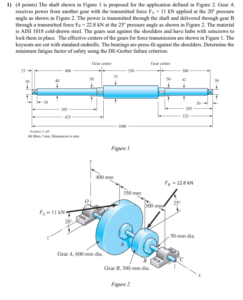
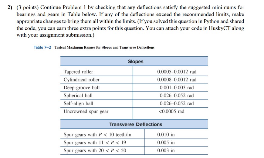
1) (4 points) The shaft shown in Figure 1 is proposed for the application defined in Figure 2. Gear A receives power from another


1) (4 points) The shaft shown in Figure 1 is proposed for the application defined in Figure 2. Gear A receives power from another gear with the transmitted force FA = 11 kN applied at the 20 pressure angle as shown in Figure 2. The power is transmitted through the shaft and delivered through gear B through a transmitted force FB = 22.8 kN at the 25 pressure angle as shown in Figure 2. The material is AISI 1018 cold-drawn steel. The gears seat against the shoulders and have hubs with setscrews to lock them in place. The effective centers of the gears for force transmission are shown in Figure 1. The keyseats are cut with standard endmills. The bearings are press-fit against the shoulders. Determine the minimum fatigue factor of safety using the DE-Gerber failure criterion. Gear center Gear center 15 400 350 300 75 30 40 50 50 42 30 30 385 425 1080 Problem 7-26 All fillets 2 mm. Dimensions in mm. Figure 1 FA-11 KN 20 400 mm FB 30 285 325 = 22.8 kN 350 mm 25 300 mm A Gear A, 600-mm dia. B Gear B, 300-mm dia. Figure 2 50-mm dia. /C 81 2) (3 points) Continue Problem 1 by checking that any deflections satisfy the suggested minimums for bearings and gears in Table below. If any of the deflections exceed the recommended limits, make appropriate changes to bring them all within the limits. (If you solved this question in Python and shared the code, you can earn three extra points for this question. You can attach your code in HuskyCT along with your assignment submission.) Table 7-2 Typical Maximum Ranges for Slopes and Transverse Deflections Tapered roller Slopes 0.0005-0.0012 rad Cylindrical roller 0.0008-0.0012 rad Deep-groove ball 0.001-0.003 rad Spherical ball 0.026-0.052 rad Self-align ball 0.026-0.052 rad Uncrowned spur gear
Step by Step Solution
There are 3 Steps involved in it
Step: 1

See step-by-step solutions with expert insights and AI powered tools for academic success
Step: 2

Step: 3

Ace Your Homework with AI
Get the answers you need in no time with our AI-driven, step-by-step assistance
Get Started


