

Question
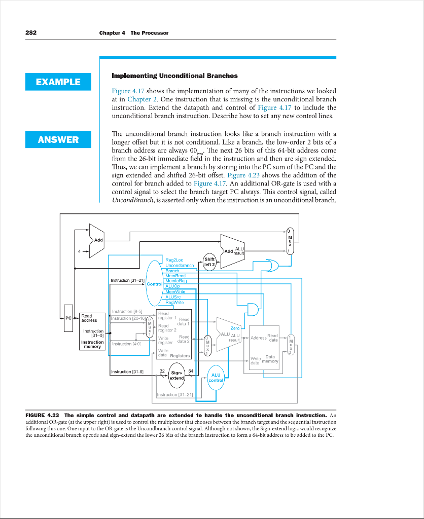
1. [5] Consider the addition of a multiplier to the CPU shown in Figure 4.23 (page 282). This addition will add 300 ps to the
1. [5] Consider the addition of a multiplier to the CPU shown in Figure 4.23 (page 282). This addition will add 300 ps to the latency of the ALU, but will reduce the number of instructions by 5% (because there will no longer be a need to emulate the multiply instruction).
What is the time and this improvement?
Without Multiplier : The maximum clock cycle time is taken by the instructionlw Clock cycle = I-Mem + Regs + Mux + ALU + D-Mem + Mux + Regs = 400 + 200 + 30 + 120 + 350 + 30 = 1130 ps.
i.e., Without Modifications: Cycle Time = 400 + 200 + 30 + 120 + 350 + 30 Cycle Time = 1130 ps
With Multiplier : The maximum clock cycle time is taken by the instructionlw Clock cycle = I-Mem + Regs + Mux + ALU + Mul + D-Mem + Mux + Regs = 400 + 200 + 30 + 120 + 300 + 350 + 30 = 1430 ps
i.e., With Modifications: Cycle Time = 1130 + 300 Cycle Time = 1430 ps
2. [5] Consider the addition of a multiplier to the CPU shown in Figure 4.23 (page 282). This addition will add 300 ps to the latency of the ALU, but will reduce the number of instructions by 5% (because there will no longer be a need to emulate the multiply instruction).
What is the achieved by adding this improvement?
Speed up performance by addition of this improvement:
Speed up = new clock cycle time/old clock cycle time
= (1130 * 100)/(95 * 1430)
0.83
3.[5] Consider the addition of a multiplier to the CPU shown in Figure 4.23 (page 282). This addition will add 300 ps to the latency of the ALU, but will reduce the number of instructions by 5% (because there will no longer be a need to emulate the multiply instruction).
What is the the new ALU can be and still result in improved performance?
With multiplier = (1000 + 10 + 10 + 200 + 10 + 100 + 300 + 30 + 2000 + 600 + 30)/1430
= 3
Without multiplier = (1000 + 200 + 10 + 2000 + 100 + 30 + 10 + 10 + 500 + 30)/1130
3.44
Difference of cost (per unit) = without multiplier - with multiplier
= 3.44 - 3.14
= 0.3
Ratio of performance = cost of improvement/cost of without improvement
= 3.44/3.14
1.10
Performance = Ratio/Speed up
= 1.10/0.83
1.32
The slowest the new ALU can be is 1.32ps to still result in improved performance
4. [5] LDUR is instruction with the longest latency on the CPU from Section 4.4 (page 271-283). If we modified LDUR and STUR so that there was no offset (i.e., the address to be loaded from/stored to must be calculated and placed in Rd before calling LDUR/ STUR), then no instruction would use both the ALU and Data memory. This would allow us to reduce the clock cycle time. However, it would also increase the number of instructions, because many LDUR and STUR instructions would need to be replaced with LDUR/ADD or STUR/ADD combinations.
What would the new clock cycle time be?
5. [5] LDUR is instruction with the longest latency on the CPU from Section 4.4 (page 271-283). If we modified LDUR and STUR so that there was no offset (i.e., the address to be loaded from/stored to must be calculated and placed in Rd before calling LDUR/ STUR), then no instruction would use both the ALU and Data memory. This would allow us to reduce the clock cycle time. However, it would also increase the number of instructions, because many LDUR and STUR instructions would need to be replaced with LDUR/ADD or STUR/ADD combinations.
What is the primary factor that influences whether a program will run faster or slower on the new CPU? 
Step by Step Solution
There are 3 Steps involved in it
Step: 1

Get Instant Access to Expert-Tailored Solutions
See step-by-step solutions with expert insights and AI powered tools for academic success
Step: 2

Step: 3
Ace Your Homework with AI
Get the answers you need in no time with our AI-driven, step-by-step assistance
Get Started
Multidimensional Array Data Management In Databases
Authors: Florin Rusu
1st Edition
1638281483, 978-1638281481