Answered step by step
Verified Expert Solution
Link Copied!

Question

1 Approved Answer

1. Access the circuits simulator for experiment 1 at: http:[[tinyurlcomlyBspmevx 2. Take notice of several key tools on your screen: a. Along the bottom you
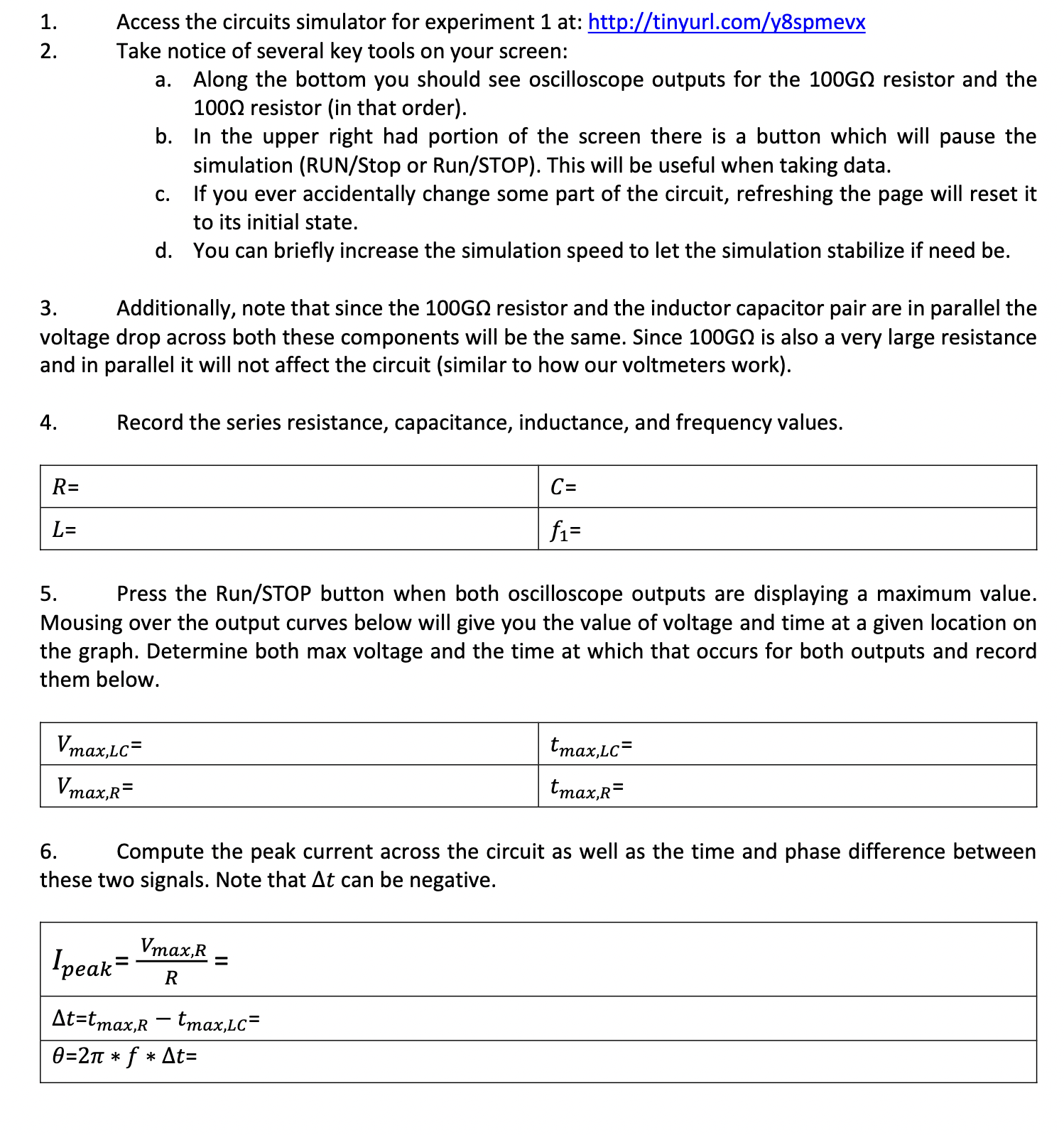
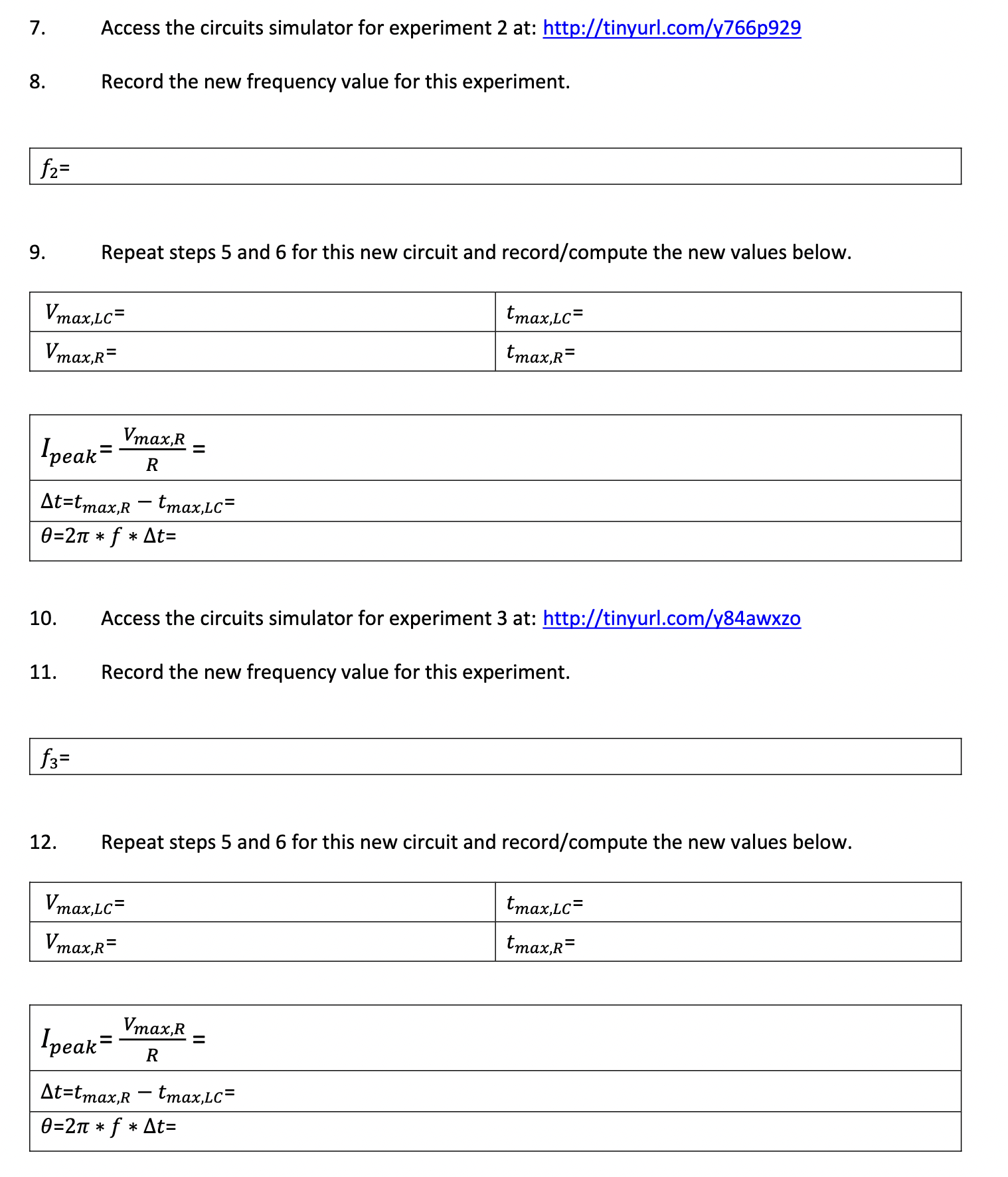
image text in transcribedimage text in transcribedimage text in transcribedimage text in transcribedimage text in transcribed
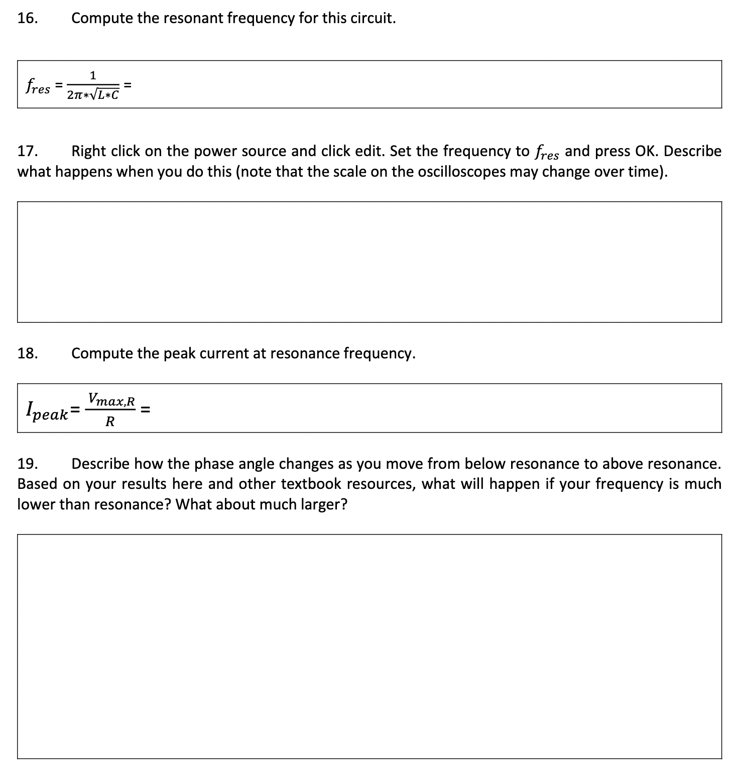
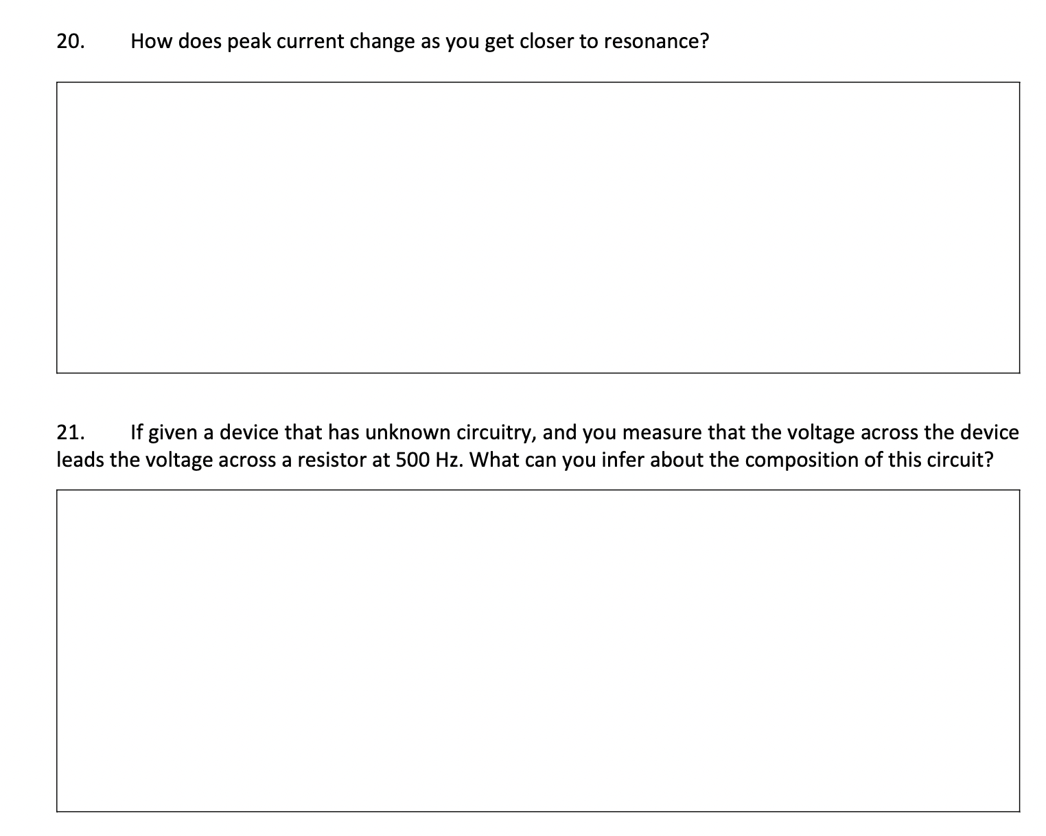
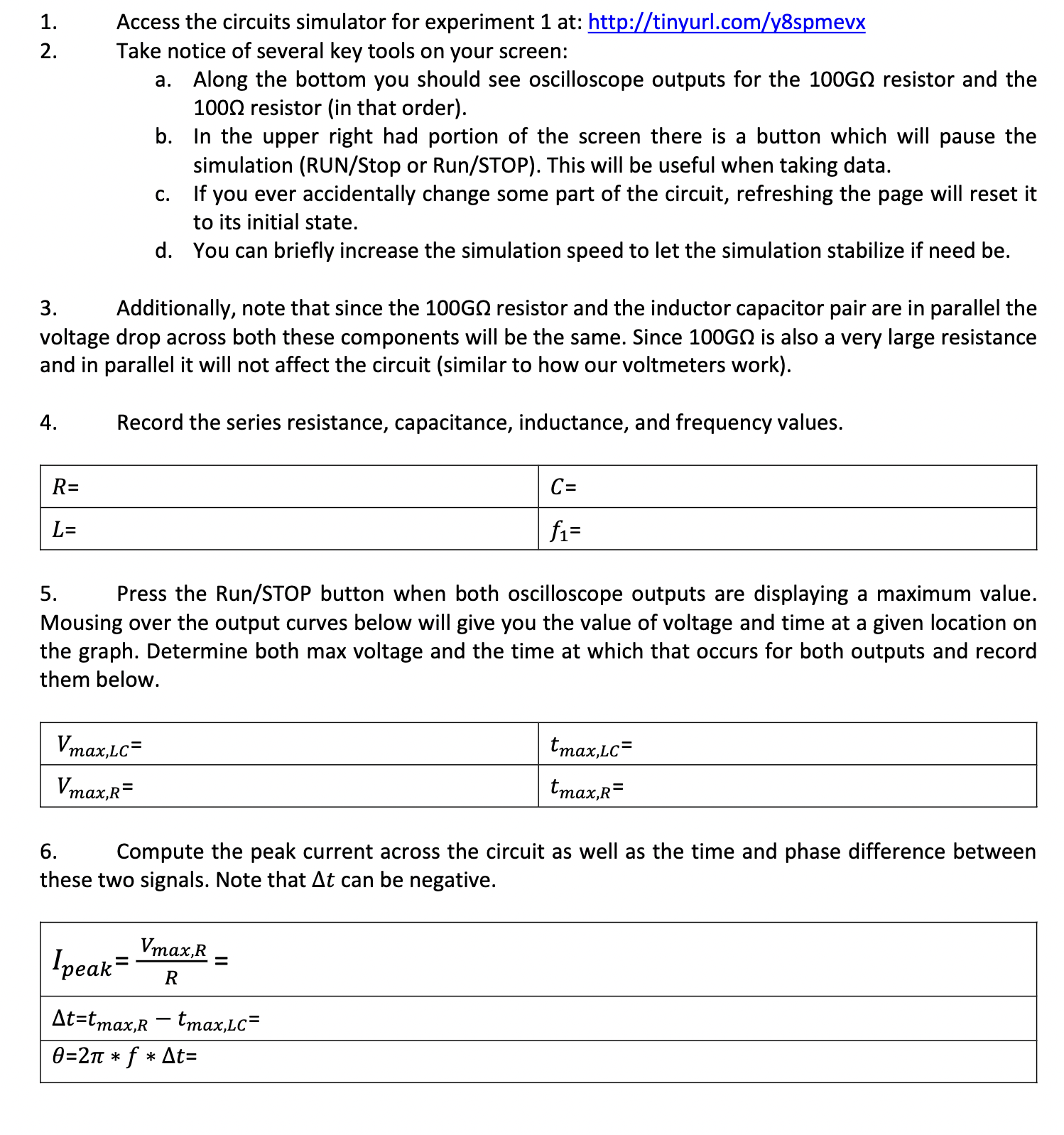
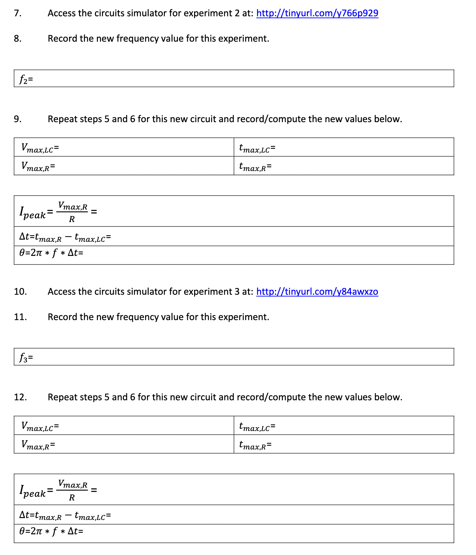
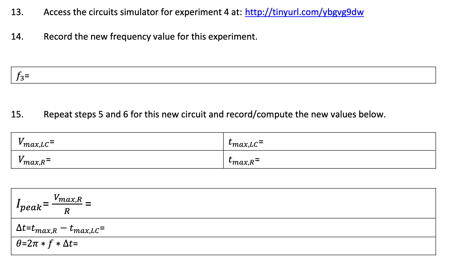
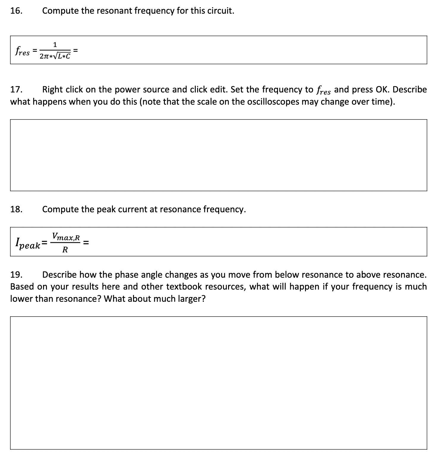
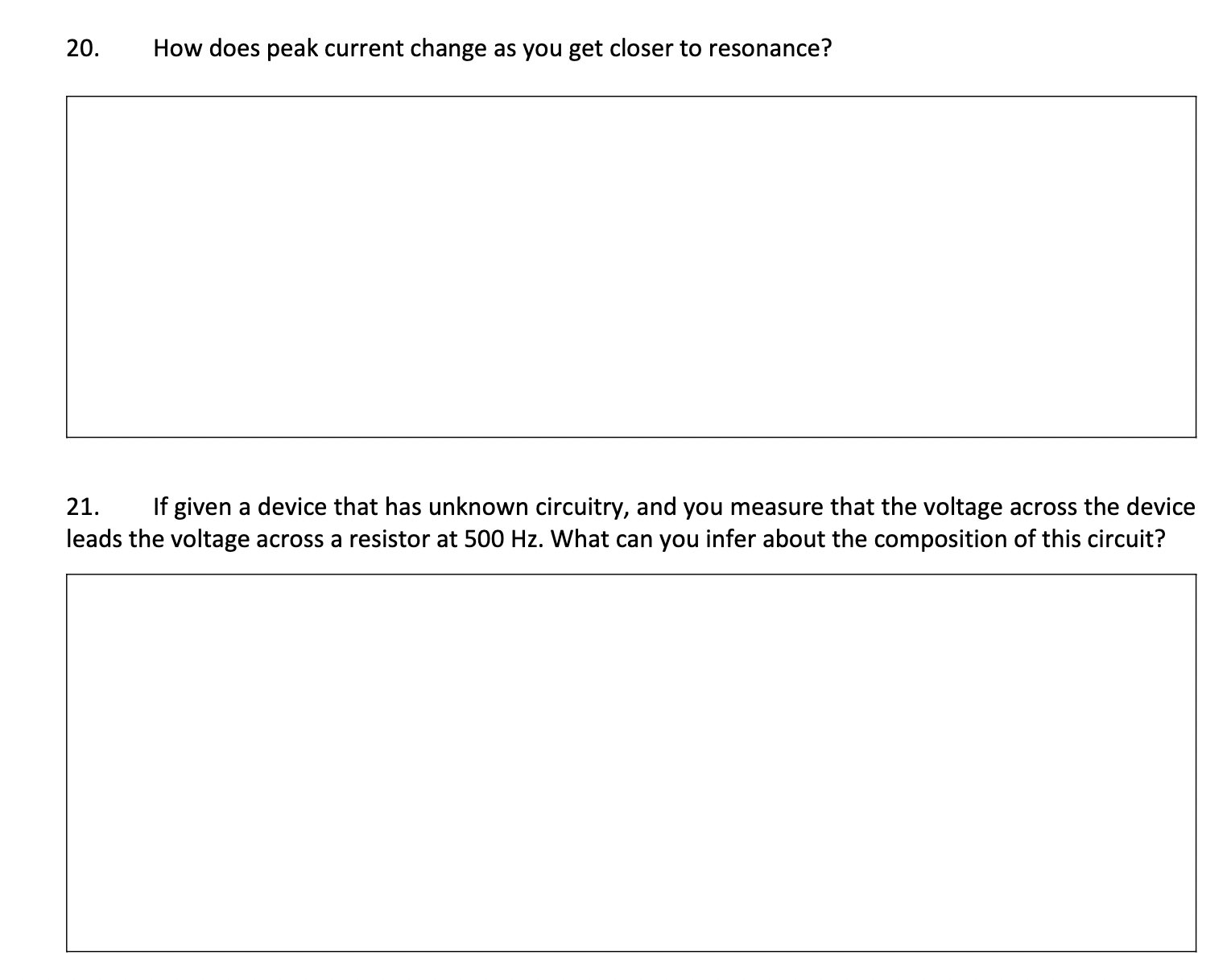
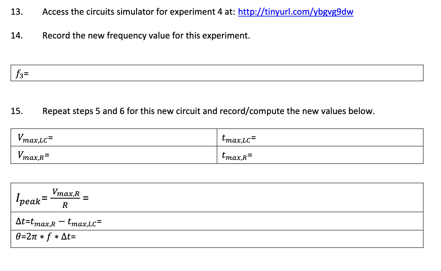
1. Access the circuits simulator for experiment 1 at: http:[[tinyurlcomlyBspmevx 2. Take notice of several key tools on your screen: a. Along the bottom you should see oscilloscope outputs for the 10060 resistor and the 1000 resistor (in that order). b. In the upper right had portion of the screen there is a button which will pause the simulation (RUN/Stop or Run/STOP). This will be useful when taking data. c. If you ever accidentally change some part of the circuit, refreshing the page will reset it to its initial state. d. You can briefly increase the simulation speed to let the simulation stabilize if need be. 3. Additionally, note that since the 10060 resistor and the inductor capacitor pair are in parallel the voltage drop across both these components will be the same. Since 1006!) is also a very large resistance and in parallel it will not affect the circuit (similar to how our voltmeters work). 4. Record the series resistance, capacitance, inductance, and frequency values. 5. Press the Run/STOP button when both oscilloscope outputs are displaying a maximum value. Mousing over the output curves below will give you the value of voltage and time at a given location on the graph. Determine both max voltage and the time at which that occurs for both outputs and record them below. 6. Compute the peak current across the circuit as well as the time and phase difference between these two signals. Note that At can be negative. 7. Access the circuits simulator for experiment 2 at: httptinvurlxoml9929 8. Record the new frequency value for this experiment. 10. Access the circuits simulator for experiment 3 at: http:[ZtinyurLcomZyS4awxzo 11. Record the new frequency value for this experiment. 12. Repeat steps 5 and 6 for this new circuit and record/compute the new values below. 13. Access the circuits simulator for experiment 4 at: httptinyurl.com[ybggg9dw 14. Record the new frequency value for this experiment. f3= 15. Repeat steps 5 and 6 for this new circuit and record/compute the new values below. 16. Compute the resonant frequency for this circuit. 1 res - 21raqu=kC _ 17. Right click on the power source and click edit. Set the frequency to es and press OK. Describe what happens when you do this (note that the scale on the oscilloscopes may change over time). 18. Compute the peak current at resonance frequency. Vmax,R [peak= = R 19. Describe how the phase angle changes as you move from below resonance to above resonance. Based on your results here and other textbook resources, what will happen if your frequency is much lower than resonance? What about much larger? 20. How does peak current change as you get closer to resonance? 21. If given a device that has unknown circuitry, and you measure that the voltage across the device leads the voltage across a resistor at 500 Hz. What can you infer about the composition of this circuit
Step by Step Solution

There are 3 Steps involved in it

Step: 1

blur-text-image

Get Instant Access to Expert-Tailored Solutions

See step-by-step solutions with expert insights and AI powered tools for academic success

Step: 2

blur-text-image_2

Step: 3

blur-text-image_3

Ace Your Homework with AI

Get the answers you need in no time with our AI-driven, step-by-step assistance

Get Started

Recommended Textbook for

Physics For Scientists And Engineers A Strategic Approach With Modern Physics

Authors: Randall D. Knight

3rd Edition

0321740904, 978-0321740908

More Books

Students also viewed these Physics questions