Answered step by step
Verified Expert Solution
Link Copied!

Question

1 Approved Answer

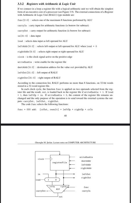
1) Adapt the previously defined ALU in Figure 1.17 to the set of function just defined in 3.3.2 Registers with Arithmetic & Logic Unit. 2)

1) Adapt the previously defined ALU in Figure 1.17 to the set of function just defined in 3.3.2 Registers with Arithmetic & Logic Unit.
2) For the RALU unit defined in 3.3.2 Registers with Arithmetic & Logic Unit design the sequence of commands, like in Table 3.2, which perform the following sequence of operations: load two numbers (17 and 4) in register file, subtract them, multiply the result by 4, add with 44, divide by 2, and send out the result on the left output.
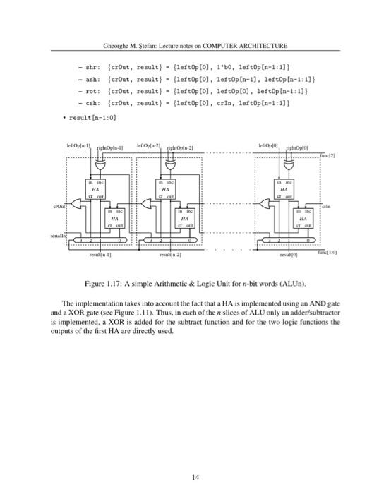
image text in transcribed
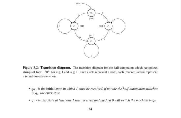
Gheorgho M. Stefan: Lecture noess on COMPUTER ARCHITECTURE Figure 1.17: A simple Arithmetic \& Logic Unit for n-bit words (ALUn). The implementation takes into account the fact that a HA is implemented using an AND gate and a XOR gate (see Figure 1.11). Thus, in each of the n slices of ALU only an adder/subtractor is implemented, a XOR is added for the subtract function and for the two logic functions the outputs of the first HA are directly used. 3.3.2 Registers with Arithmetic \& Logic Unit If we consect in a loop a register file with a logical-arithmetic unit we will obtain the simplest form of an evecutive core of a processor (see Figure 3.9). The external connections of a Register with Arithmetic \& Logic Unit (RALU) type modale are: func [2:0] : selects one of the maximum 8 functions performed by ALU carryin : camy input for arithmetic functions (is boeros for subtract) carryout : carry oatpot for arithmetic fuection (is borrow for mabcract) in [31:0] : daka ieput toad : selects data inpot as left operand for AL.U leftaddr [4:0] : selects left output or left operand for AL.U when load =0 right Addr [4:0] : selects right ousput or righ operand for ALU eleck: is the elock signal active on the positive edge uriteEnable : write enable for the regater file deatAddr [4:0] : destanatioe address for the salue out provided by AL.U left0ut [31:0] : left output of R.ALU rightout [31:0] : right output of RALU Accorting to the connection list, RALU performs no more than 8 functions, on 32 -bit words stored in a 32 -word register file. In each clock cycle, the function func is applicd on fwo operands selected from the reg. ister file and the resalt, out, is loaded buck in the register file if uriteEbable = 1. If load - 1. then lef eop = in. If uriteEnable =0, the ccatent of the register file remains anchanged and the oely purpose of the operatioe is to send toward the exemal systems the outpatts: earryout, leftout, rightout. The code func selects the following function: func=000add:{crDut,reault)=left0p+rightop+crIn Figure 3.2: Transition diagram. The transition diagram for the half-automaton which recognizes strings of form 1"10m, for n1 and m1. Each circle represent a state, each (marked) arrow represent a (conditioned) transition. - q0 - is the initial state in which 1 must be received, if not the the half-automaton switches in q3, the error state - q1 - in this state at least one I was received and the first 0 will switch the machine in q2

Step by Step Solution

There are 3 Steps involved in it

Step: 1

blur-text-image

Get Instant Access to Expert-Tailored Solutions

See step-by-step solutions with expert insights and AI powered tools for academic success

Step: 2

blur-text-image

Step: 3

blur-text-image

Ace Your Homework with AI

Get the answers you need in no time with our AI-driven, step-by-step assistance

Get Started

Recommended Textbook for

Databases DeMYSTiFieD

Authors: Andy Oppel

2nd Edition

0071747990, 978-0071747998

More Books

Students also viewed these Databases questions