Answered step by step
Verified Expert Solution
Question
1 Approved Answer
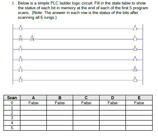
1. Below is a simple PLC ladder logic circuit. Fill in the state table to show the status of each bit in memory at the

1. Below is a simple PLC ladder logic circuit. Fill in the state table to show the status of each bit in memory at the end of each of the first 5 program scans. (Note: The answer in each row is the status of the bits after ???. Scan 0 1 2 3 4 5 False False False False False
Step by Step Solution
There are 3 Steps involved in it
Step: 1

Get Instant Access to Expert-Tailored Solutions
See step-by-step solutions with expert insights and AI powered tools for academic success
Step: 2

Step: 3

Ace Your Homework with AI
Get the answers you need in no time with our AI-driven, step-by-step assistance
Get Started


