1. Calculate the forces acting on the piston at design pressure. 2. Perform static calculation to estimate fastener size based on the worst-case scenario.


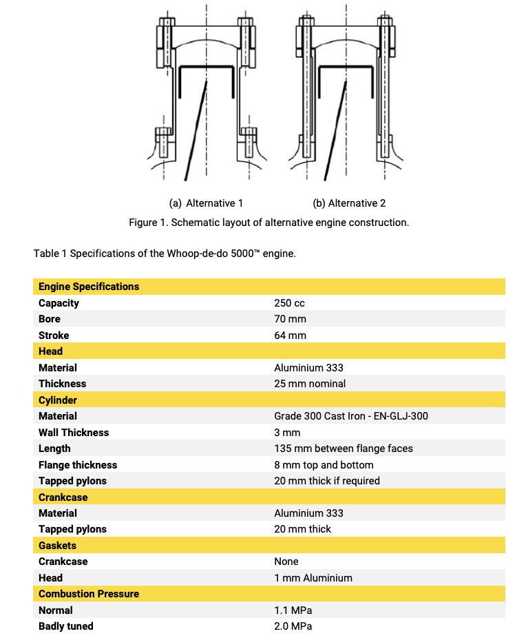
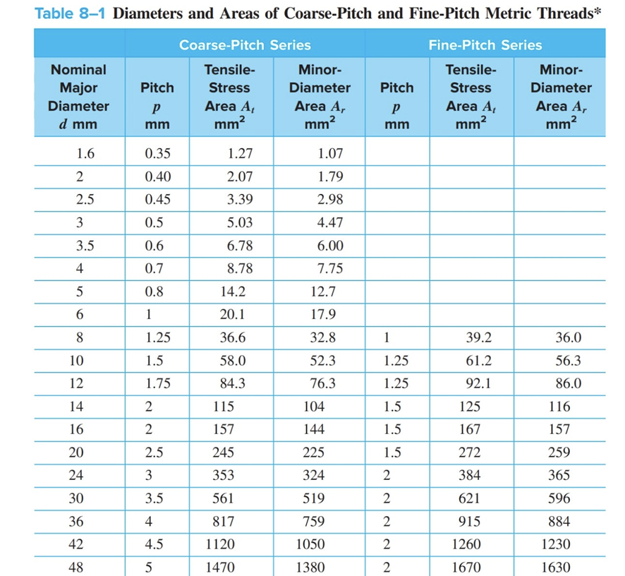
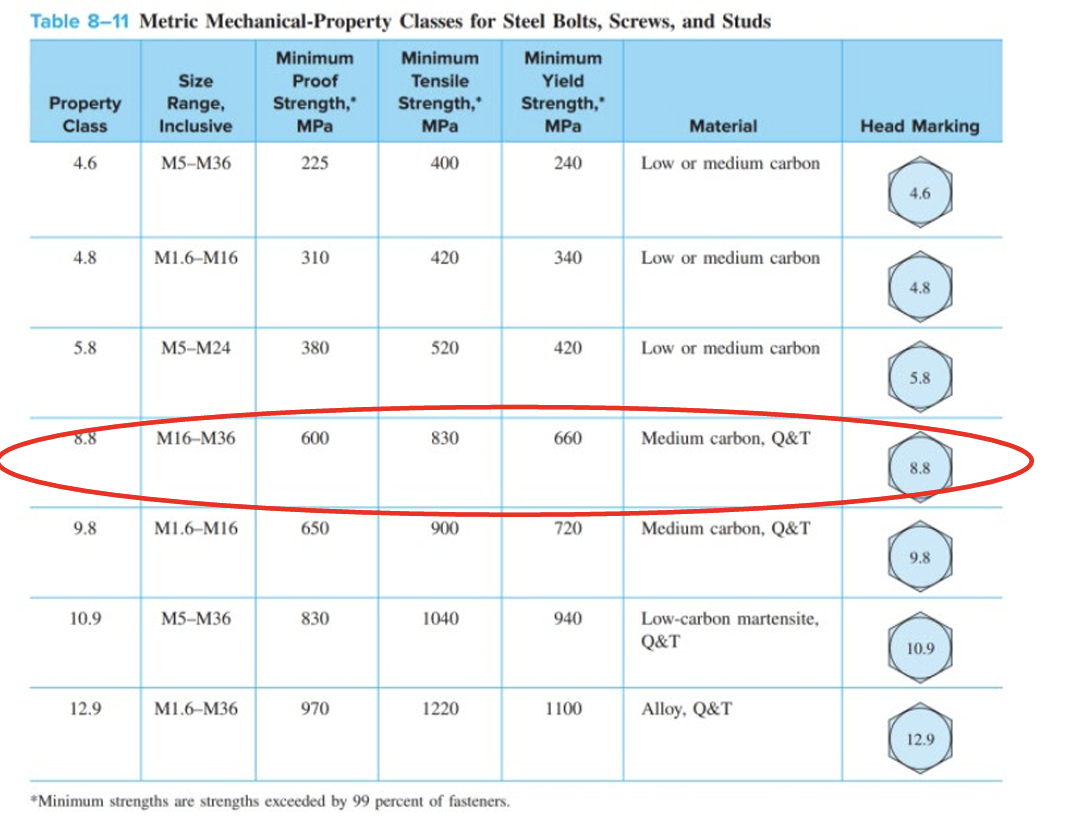
1. Calculate the forces acting on the piston at design pressure. 2. Perform static calculation to estimate fastener size based on the worst-case scenario. 3. Construct the spring model of the system and determine spring rates, k. 4. Determine the pretension force in fasteners. 5. Produce the spring rate diagram for the worst-case scenario. 6. Conduct a failure analysis of the fasteners. a. Determine the factor of safety against fastener yielding (load factor n). b. Determine the factor of safety against joint separation no. (a) Alternative 1 (b) Alternative 2 Figure 1. Schematic layout of alternative engine construction. Table 1 Specifications of the Whoop-de-do 5000 engine. Engine Specifications Capacity Bore Stroke Head Material Thickness 250 cc 70 mm 64 mm Cylinder Material Wall Thickness Length Flange thickness Tapped pylons Aluminium 333 25 mm nominal Grade 300 Cast Iron - EN-GLJ-300 3 mm 135 mm between flange faces 8 mm top and bottom 20 mm thick if required Crankcase Material Tapped pylons Aluminium 333 20 mm thick Gaskets Crankcase Head Combustion Pressure Normal Badly tuned None 1 mm Aluminium 1.1 MPa 2.0 MPa Table 8-1 Diameters and Areas of Coarse-Pitch and Fine-Pitch Metric Threads* Coarse-Pitch Series Fine-Pitch Series Nominal Major Diameter Tensile- Minor- Tensile- Pitch Stress Diameter Pitch Stress Minor- Diameter P Area A Area A, P Area A Area A, d mm mm mm mm mm mm mm 1.6 0.35 1.27 1.07 2 0.40 2.07 1.79 2.5 0.45 3.39 2.98 3 0.5 5.03 4.47 3.5 0.6 6.78 6.00 4 0.7 8.78 7.75 5 0.8 14.2 12.7 9 1 20.1 17.9 8 1.25 36.6 32.8 1 39.2 36.0 10 1.5 58.0 52.3 1.25 61.2 56.3 12 1.75 84.3 76.3 1.25 92.1 86.0 14 2 115 104 1.5 125 116 16 2 157 144 1.5 167 157 20 2.5 245 225 1.5 272 259 24 3 353 324 30 3.5 561 519 36 4 817 759 42 4.5 1120 1050 2222 2 384 365 2 621 596 2 915 884 2 1260 1230 48 5 1470 1380 2 1670 1630 Table 8-11 Metric Mechanical-Property Classes for Steel Bolts, Screws, and Studs Minimum Minimum Minimum Property Class Size Range, Inclusive Proof Strength," MPa Tensile Strength, MPa Yield Strength, MPa Material Head Marking 4.6 M5-M36 225 400 240 Low or medium carbon 4.6 4.8 M16 M16 310 420 340 Low or medium carbon 4.8 5.8 M5-M24 380 520 420 Low or medium carbon 5.8 8.8 M16-M36 600 830 660 Medium carbon, Q&T 8.8 9.8 M1.6 M16 650 900 720 Medium carbon, Q&T 9.8 10.9 M5-M36 830 1040 940 Low-carbon martensite, Q&T 10.9 12.9 M1.6-M36 970 1220 1100 Alloy, Q&T 12.9 *Minimum strengths are strengths exceeded by 99 percent of fasteners.
Step by Step Solution
There are 3 Steps involved in it
Step: 1

See step-by-step solutions with expert insights and AI powered tools for academic success
Step: 2

Step: 3

Ace Your Homework with AI
Get the answers you need in no time with our AI-driven, step-by-step assistance
Get Started


