Answered step by step
Verified Expert Solution
Question
1 Approved Answer
Declare an entity called seven_segment_agent with the following generic configu- ration parameters: Parameter lamp_mode decimal_support boolean implementer lamp_configuration revision natural natural Description Configuration of
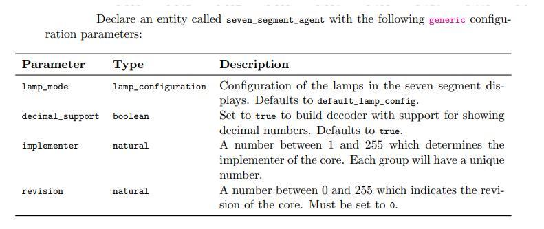
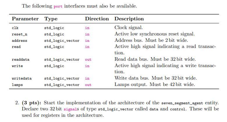

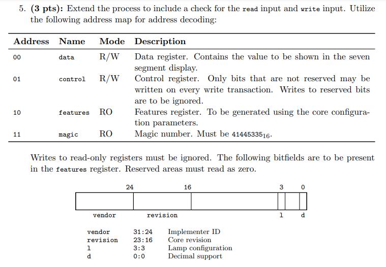
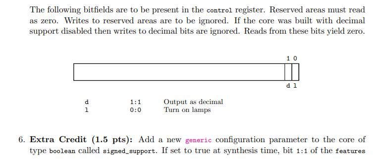

Declare an entity called seven_segment_agent with the following generic configu- ration parameters: Parameter lamp_mode decimal_support boolean implementer lamp_configuration revision natural natural Description Configuration of the lamps in the seven segment dis- plays. Defaults to default_lamp_config. Set to true to build decoder with support for showing decimal numbers. Defaults to true. A number between 1 and 255 which determines the implementer of the core. Each group will have a unique number. A number between 0 and 255 which indicates the revi- sion of the core. Must be set to 0. The following port interfaces must also be available. Parameter Type Direction Description Clock signal. Active low synchronous reset signal. Address bus. Must be 2 bit wide. Active high signal indicating a read transac- tion. clk reset_n address read readdata write writedata lamps std_logic in std_logic in std_logic_vector in std_logic in std_logic_vector std_logic out in std_logic_vector in std_logic_vector out Read data bus. Must be 32 bit wide. Active high signal indicating a write transac- tion. Write data bus. Must be 32 bit wide. Lamps output. Must be 42 bit wide. 2. (3 pts): Start the implementation of the architecture of the seven_segment_agent entity. Declare two 32 bit signals of type std_logic_vector called data and control. These will be used for registers in the architecture. 3. (3 pts): Implement a function which takes an array of six elements of type seven_segment_config as an input and returns a std_logic_vector. The function concatenates all entries of each seven_segment_config record starting from g to a. The lowest seven bits of the resulting std_logic_vector should map to entry 0 of the array with the 7th bit and 1st bit being mapped to the g and a, respectively. 4. (3 pts): Implement a process which is triggered on changes to the clock signal. On a rising edge of the clock signal, the process shall check the state of the reset signal. If active, the data and control registers shall be set to 0. 5. (3 pts): Extend the process to include a check for the read input and write input. Utilize the following address map for address decoding: Description Data register. Contains the value to be shown in the seven segment display. Control register. Only bits that are not reserved may be written on every write transaction. Writes to reserved bits are to be ignored. Features register. To be generated using the core configura- tion parameters. Magic number. Must be 4144533516. Address Name Mode R/W R/W 00 01 10 11 data control features RO magic Writes to read-only registers must be ignored. The following bitfields are to be present in the features register. Reserved areas must read as zero. RO 1 vendor revision d vendor 24 revision 31:24 23:16 3:3 0:0 16 Implementer ID Core revision Lamp configuration Decimal support 3 0 1 d The following bitfields are to be present in the control register. Reserved areas must read as zero. Writes to reserved areas are to be ignored. If the core was built with decimal support disabled then writes to decimal bits are ignored. Reads from these bits yield zero. d TP 1 1:1 0:0 Output as decimal Turn on lamps 10 d 1 6. Extra Credit (1.5 pts): Add a new generic configuration parameter to the core of type boolean called signed_support. If set to true at synthesis time, bit 1:1 of the features register reads as 1 and writes to bit 3:3 of the control register are allowed. If the latter bit is set when the decimal bit in the control register is set, the number in data shall be treated as a signed negative number and displayed on the lamps as such. 7. Extra Credit (1.5 pts): Add a new generic configuration parameter to the core of type boolean called blank_zeros_support. If set to true at synthesis time, bit 2:2 of the features register reads as 1 and writes to bit 2:2 of the control register are allowed. If the latter bit is set when the decimal bit is set in the control register, the output on the lamps shall omit any leading zeros.
Step by Step Solution
There are 3 Steps involved in it
Step: 1
Based on the provided information heres the implementation of the architecture for the sevensegmenta...
Get Instant Access to Expert-Tailored Solutions
See step-by-step solutions with expert insights and AI powered tools for academic success
Step: 2

Step: 3

Ace Your Homework with AI
Get the answers you need in no time with our AI-driven, step-by-step assistance
Get Started


