Answered step by step
Verified Expert Solution
Question
1 Approved Answer
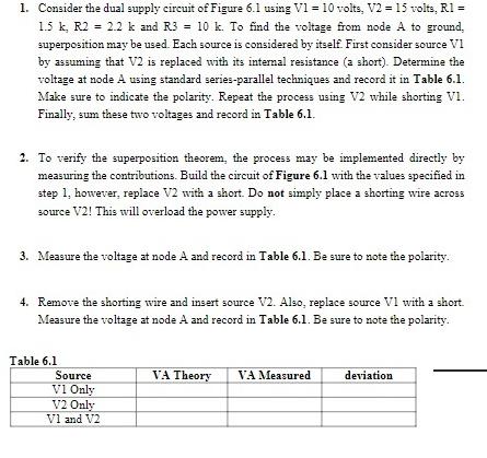
1. Consider the dual supply circuit of Figure 6.1 using V1 = 10 volts, V2 = 15 volts, R1 = 1.5 k, R2 =


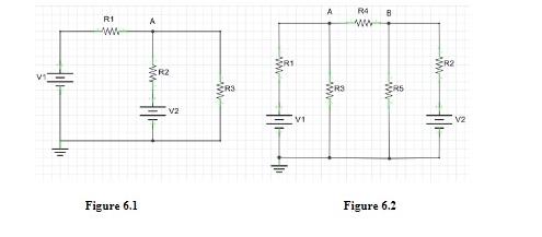
1. Consider the dual supply circuit of Figure 6.1 using V1 = 10 volts, V2 = 15 volts, R1 = 1.5 k, R2 = 2.2 k and R3 = 10 k. To find the voltage from node A to ground. superposition may be used. Each source is considered by itself. First consider source VI by assuming that V2 is replaced with its internal resistance (a short). Determine the voltage at node A using standard series-parallel techniques and record it in Table 6.1. Make sure to indicate the polarity. Repeat the process using V2 while shorting VI. Finally, sum these two voltages and record in Table 6.1. 2. To verify the superposition theorem, the process may be implemented directly by measuring the contributions. Build the circuit of Figure 6.1 with the values specified in step 1, however, replace V2 with a short. Do not simply place a shorting wire across source V2! This will overload the power supply. 3. Measure the voltage at node A and record in Table 6.1. Be sure to note the polarity. 4. Remove the shorting wire and insert source V2. Also, replace source VI with a short. Measure the voltage at node A and record in Table 6.1. Be sure to note the polarity. Table 6.1 Source V1 Only V2 Only V1 and V2 VA Theory VA Measured deviation R1 Www Figure 6.1 A R2 V2 www. VI A R4 B ww RS Figure 6.2 www.
Step by Step Solution
★★★★★
3.44 Rating (160 Votes )
There are 3 Steps involved in it
Step: 1
1 To find the voltage at node A using superposition in the dual supply circuit 1 First consider source V1 only by replacing V2 with a short circuit Analyze the circuit using standard seriesparallel te...
Get Instant Access to Expert-Tailored Solutions
See step-by-step solutions with expert insights and AI powered tools for academic success
Step: 2

Step: 3

Ace Your Homework with AI
Get the answers you need in no time with our AI-driven, step-by-step assistance
Get Started


