

Question: 1 Consider the multiplexer circuit shown on page 160 (or handout). Give the output value of F for the following input values: D D D
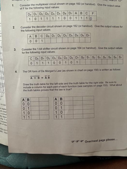
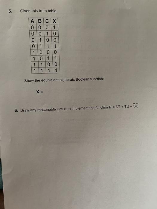
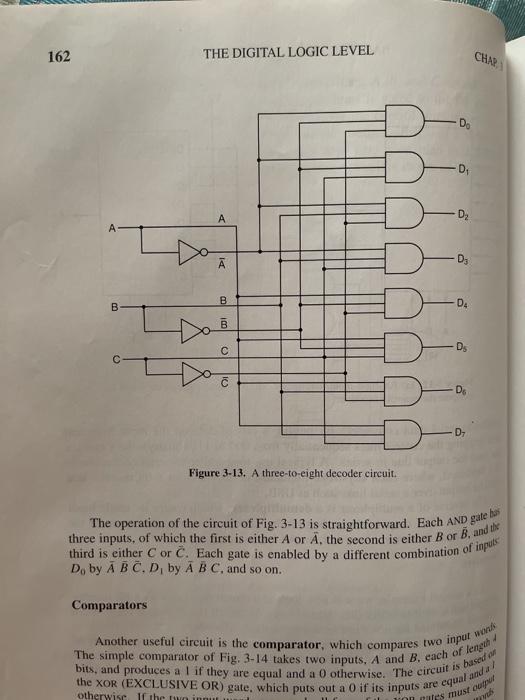
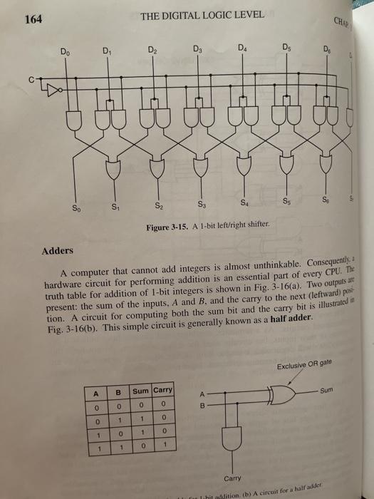
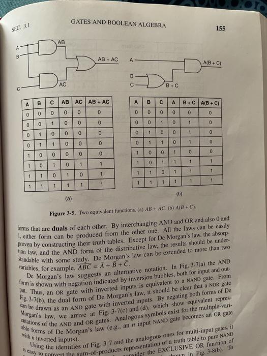
1 Consider the multiplexer circuit shown on page 160 (or handout). Give the output value of F for the following input values: D D D D D Ds D. D7 A B C F 1 0 1 1 1 1 0 0 1 1 1 0 Consider the decoder circuit shown on page 162 (or handout). Give the output values for the following input values: A B C D D D D D D D D 0 0 1 2. 3 Consider the 1-bit shifter circuit shown on page 164 (or handout). Give the output values for the following input values C D D D D D D D D S S S S S SS SS S 0 1 1 1 0 0 1 0 1 The OR form of De Morgan's Law (as shown in chart on page 156) is written as follows: A + B = AB Draw the truth table for the left side and the truth table for the right side. Be sure to include a column for each part of each function (see samples on page 155). What about the truth tables proves that the law is true? Ash symple 0 0 0 1 1 0 1 1 A B 0 0 0 1 1 0 1 1 is wird the Fig 3- temami sle of a Ship Overext page please... 5. Given this truth table. A B C X 0 0 0 1 0 0 1 0 0 1 0 0 0 1 1 1 1 0 0 0 1 0 1 1 1 1 0 0 1 1 1 1 Show the equivalent algebraic Boolean function: X= 6. Draw any reasonable circuit to implement the function R = ST + TU + SU 160 THE DIGITAL LOGIC LEVEL for an eight-input multiplexer. The three control lines, A, B, and C, encode number that specifies which of the eight input lines is gated to the OR thence to the output. No matter what value is on the control lines, seven AND gates will always output 0; the other one may output either 0 or 1, dep on the value of the selected input line. Each AND gate is enabled by a de combination of the control inputs. The multiplexer circuit is shown in Fig. 21 Do- D D2 B D D4 D5 B. B DO D A B B Cal &&& A B C Figure 3-11. An eight-input multiplexer circuit as shown in Fig. 3-12(b). For each combination of A, B, and one of the Using the multiplexer, we can implement the majority function of Fig. input lines is selected. Each input is wired to either (logical I)or and cal O). The algorithm for wiring the inputs is simple: input D is the same value in rowi of the truth table. In Fig. 3-3(a), rows 0, 1, 2, and are not restanding inputs are grounded, the remaining rows are 1. so they are w ale of the variables can be implemente 162 THE DIGITAL LOGIC LEVEL CH D D Ia D B B D B DS C 1 -D D- Figure 3-13. A three-to-eight decoder circuit. The operation of the circuit of Fig. 3-13 is straightforward. Each AND gate bus third is either C or C. Each gate is enabled by a different combination of inputs D. by A B C D by A B C, and so on. Comparators The simple comparator of Fig. 3-14 takes two inputs, A and B, each of length Another useful circuit is the comparator, which compares two input was bits, and produces a 1 if they are equal and a 0 otherwise, The circuit is based on otherwise the ini non mutes must ou the XOR (EXCLUSIVE OR) gate, which puts out a 0 if its inputs equal anda/ 164 THE DIGITAL LOGIC LEVEL CHA D Do D2 D D. D D S4 So Ss Si S S2 Figure 3-15. A l-bit left/right shifter. Adders A computer that cannot add integers is almost unthinkable. Consequently, hardware circuit for performing addition is an essential part of every CPU. The truth table for addition of 1-bit integers is shown in Fig. 3-16(a). Two outputs present: the sum of the inputs, A and B. and the carry to the next (leftward) post tion. A circuit for computing both the sum bit and the carry bit is illustrated in Fig. 3-16(b). This simple circuit is generally known as a half adder. Exclusive OR gate B Sum Carry Sum A 0 o O B oo 0 1 1 0 1 1 0 1 1 1 1 0 Carry lahir addition (b) A circuit for a halfadder GATES AND BOOLEAN ALGEBRA SEC 3.1 155 AB A B AB + AC A A(B+C) B AC B+C c AB AC AB + AC A B A B+C A(B+C) 0 0 0 0 0 lolol All 0 0 O Oo ololo 1 0 0 ololololo 1 1 1 0 0 0 1 1 0 1 1 0 0 -0-0-0-0 --OOOOOO 100000-0- 1 0 0 1 0 0 1 0 0 1 1 1 1 1 1 1 0 1 1 1 1 1 1 1 1 1 1 1 1 1 1 1 1 1 1 (b) (a) Figure 3-5. Two equivalent functions. (a) AB + AC. (b) A(B+C). forms that are duals of each other. By interchanging AND and OR and also and 1. either form can be produced from the other one. All the laws can be easily proven by constructing their truth tables. Except for De Morgan's law, the absorp- tion law, and the AND form of the distributive law, the results should be under- Standable with some study. De Morgan's law can be extended to more than two variables, for example, ABC = A + B + C. form is shown with negation indicated by inversion bubbles, both for input and out- De Morgan's law suggests an alternative notation. In Fig. 3-7(a) the AND put. Thus, an OR gate with inverted inputs is equivalent to a NAND gate. From Fig. 3-7(b), the dual form of De Morgan's law, it should be clear that a NOR gate can be drawn as an AND gate with inverted inputs. By negating both forms of De Morgan's law, we arrive at Fig. 3-7(e) and (d), which show equivalent repres- Citations of the AND and OR gates. Analogous symbols exist for the multiple-vari- able forms of De Morgan's law (e.g., an n input NAND gate becomes an OR gate easy to convert the sum-of-products representation of a truth table to pure NAND Using the identities of Fig. 3.7 and the analogous ones for multi-input gates, it with n inverted inputs). onsider the EXCLUSIVE OR function of hown in Fig. 3-8(b). To
Step by Step Solution
There are 3 Steps involved in it

Get step-by-step solutions from verified subject matter experts