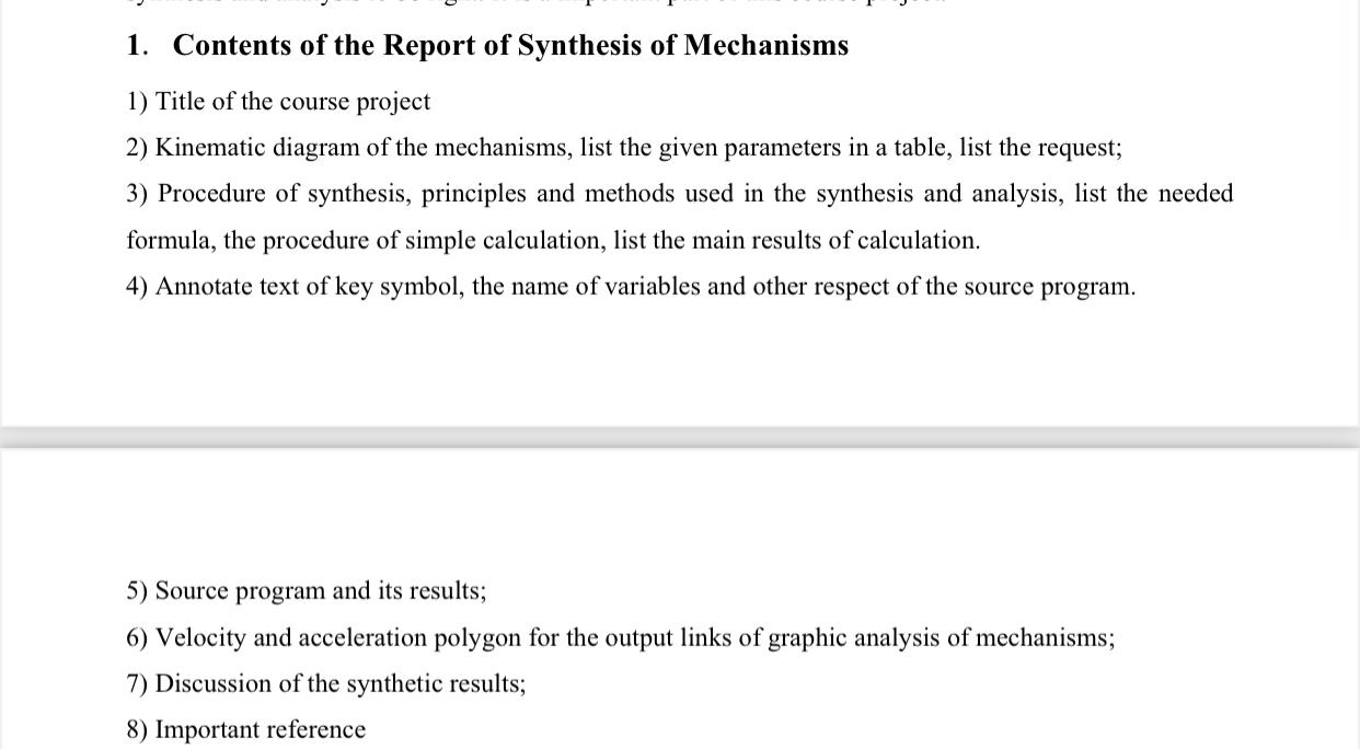
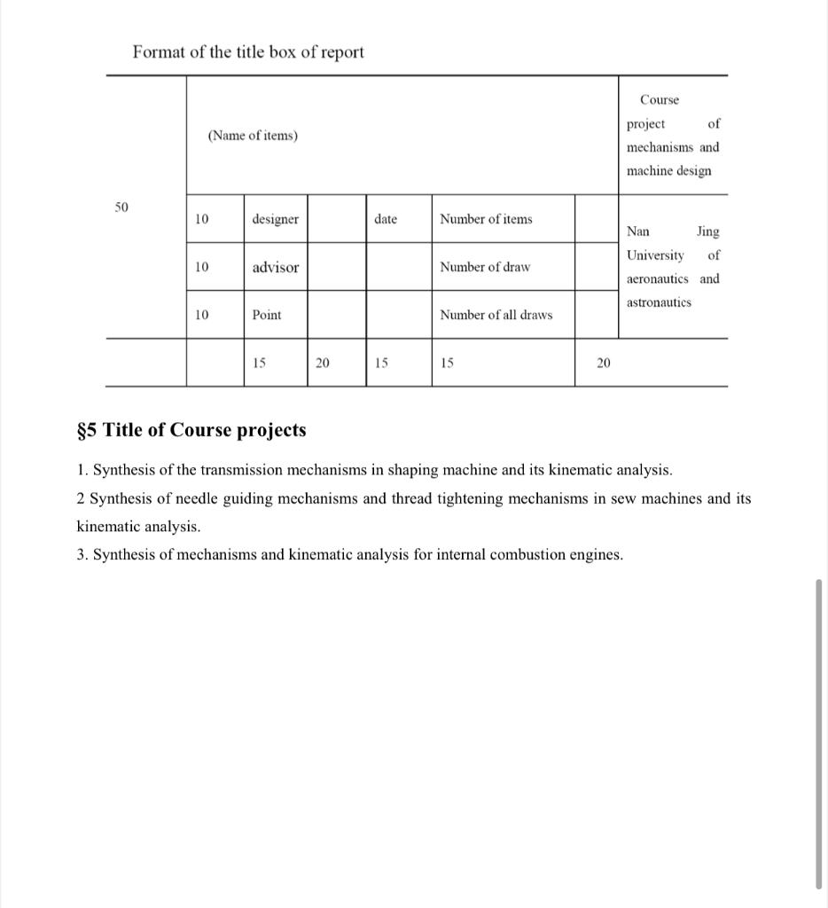
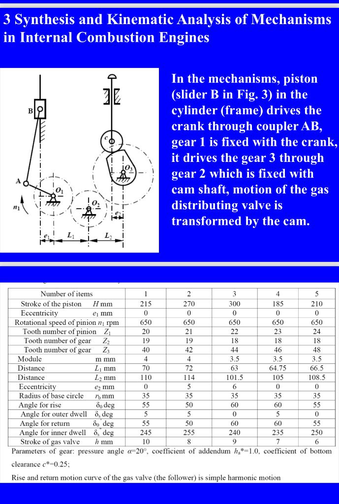
1. Contents of the Report of Synthesis of Mechanisms 1) Title of the course project 2) Kinematic diagram of the mechanisms, list the given parameters in a table, list the request; 3) Procedure of synthesis, principles and methods used in the synthesis and analysis, list the needed formula, the procedure of simple calculation, list the main results of calculation. 4) Annotate text of key symbol, the name of variables and other respect of the source program. 5) Source program and its results; 6) Velocity and acceleration polygon for the output links of graphic analysis of mechanisms; 7) Discussion of the synthetic results; 8) Important reference Format of the title box of report Course (Name of items) project of mechanisms and machine design 50 10 designer date Number of items Nan Jing University of aeronautics and 10 advisor Number of draw astronautics 10 Point Number of all draws 15 20 15 15 20 $5 Title of Course projects 1. Synthesis of the transmission mechanisms in shaping machine and its kinematic analysis. 2 Synthesis of needle guiding mechanisms and thread tightening mechanisms in sew machines and its kinematic analysis. 3. Synthesis of mechanisms and kinematic analysis for internal combustion engines. 3 Synthesis and Kinematic Analysis of Mechanisms in Internal Combustion Engines In the mechanisms, piston (slider B in Fig. 3) in the cylinder (frame) drives the crank through coupler AB, gear 1 is fixed with the crank, it drives the gear 3 through gear 2 which is fixed with cam shaft, motion of the gas distributing valve is transformed by the cam. ni L L Number of items 1 2 3 4 5 Stroke of the piston H mm 215 270 300 185 210 Eccentricity e mm 0 0 0 0 0 Rotational speed of pinion n rpm 650 650 650 650 650 Tooth number of pinion Z1 20 21 22 23 24 Tooth number of gear Z2 19 19 18 18 18 Tooth number of gear Zz 40 42 44 46 48 Module m mm 4 4 3.5 3.5 3.5 Distance L mm 70 72 63 64.75 66.5 Distance L2 mm 110 114 101.5 105 108.5 Eccentricity e2 mm 0 5 6 0 0 Radius of base circle 7 mm 35 35 35 35 35 Angle for rise o deg 55 50 60 60 55 Angle for outer dwell 8 deg 5 5 0 5 0 Angle for return do deg 55 50 60 60 55 Angle for inner dwell o, deg 245 255 240 235 250 Stroke of gas valve h mm 10 8 9 7 6 Parameters of gear: pressure angle -20, coefficient of addendum h*=1.0, coefficient of bottom clearance c*=0.25; Rise and return motion curve of the gas valve (the follower) is simple harmonic motion 1. Contents of the Report of Synthesis of Mechanisms 1) Title of the course project 2) Kinematic diagram of the mechanisms, list the given parameters in a table, list the request; 3) Procedure of synthesis, principles and methods used in the synthesis and analysis, list the needed formula, the procedure of simple calculation, list the main results of calculation. 4) Annotate text of key symbol, the name of variables and other respect of the source program. 5) Source program and its results; 6) Velocity and acceleration polygon for the output links of graphic analysis of mechanisms; 7) Discussion of the synthetic results; 8) Important reference Format of the title box of report Course (Name of items) project of mechanisms and machine design 50 10 designer date Number of items Nan Jing University of aeronautics and 10 advisor Number of draw astronautics 10 Point Number of all draws 15 20 15 15 20 $5 Title of Course projects 1. Synthesis of the transmission mechanisms in shaping machine and its kinematic analysis. 2 Synthesis of needle guiding mechanisms and thread tightening mechanisms in sew machines and its kinematic analysis. 3. Synthesis of mechanisms and kinematic analysis for internal combustion engines. 3 Synthesis and Kinematic Analysis of Mechanisms in Internal Combustion Engines In the mechanisms, piston (slider B in Fig. 3) in the cylinder (frame) drives the crank through coupler AB, gear 1 is fixed with the crank, it drives the gear 3 through gear 2 which is fixed with cam shaft, motion of the gas distributing valve is transformed by the cam. ni L L Number of items 1 2 3 4 5 Stroke of the piston H mm 215 270 300 185 210 Eccentricity e mm 0 0 0 0 0 Rotational speed of pinion n rpm 650 650 650 650 650 Tooth number of pinion Z1 20 21 22 23 24 Tooth number of gear Z2 19 19 18 18 18 Tooth number of gear Zz 40 42 44 46 48 Module m mm 4 4 3.5 3.5 3.5 Distance L mm 70 72 63 64.75 66.5 Distance L2 mm 110 114 101.5 105 108.5 Eccentricity e2 mm 0 5 6 0 0 Radius of base circle 7 mm 35 35 35 35 35 Angle for rise o deg 55 50 60 60 55 Angle for outer dwell 8 deg 5 5 0 5 0 Angle for return do deg 55 50 60 60 55 Angle for inner dwell o, deg 245 255 240 235 250 Stroke of gas valve h mm 10 8 9 7 6 Parameters of gear: pressure angle -20, coefficient of addendum h*=1.0, coefficient of bottom clearance c*=0.25; Rise and return motion curve of the gas valve (the follower) is simple harmonic motion