Question
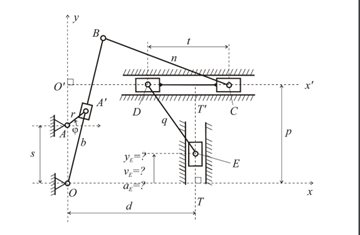
1. DESCRIPTION OF THE MECHANISM The mechanism whose kinematics is to be modelled incorporates four sliders A', C, D and E. Slider A' moves along
1. DESCRIPTION OF THE MECHANISM The mechanism whose kinematics is to be modelled incorporates four sliders A', C, D and E. Slider A' moves along the link OB, slider E moves along axis TT' which is parallel to the y-axis and at a distance d from the y-axis. Sliders D and C are rigidly connected and move along the horizontal axis O'x' which is parallel to the coordinate axis Ox and at a distance p from the coordinate axis Ox. Because of the rigid connection, sliders D and C remain constantly at a distance t. The crank AA' rotates in counter-clockwise direction, with a uniform angular velocity of w =1.5 rad/s. The crank AA' subtends an angle with the horizontal x-axis which varies within the interval [0, 2 ] ( 0 2 ). Note that the angle OBC is not fixed and varies as the links OB and BC rotate around the pin joint B. The numerical values of the parameters that fully specify the mechanism are: OA s m = = 0.45 AA r m ' 0.15 = = OB b m = = 0.70 BC n m = = 0.65 CD t m = = 0.45 DE q m = = 0.55 d m = 0.30 p m

4. Create an appropriate model and a MATLAB script for determining the velocity of point E (in m/s) on the fourth slider as a function of the crank angle in rad.
Step by Step Solution
There are 3 Steps involved in it
Step: 1

Get Instant Access to Expert-Tailored Solutions
See step-by-step solutions with expert insights and AI powered tools for academic success
Step: 2

Step: 3

Ace Your Homework with AI
Get the answers you need in no time with our AI-driven, step-by-step assistance
Get Started


