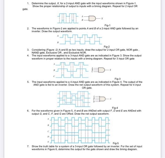
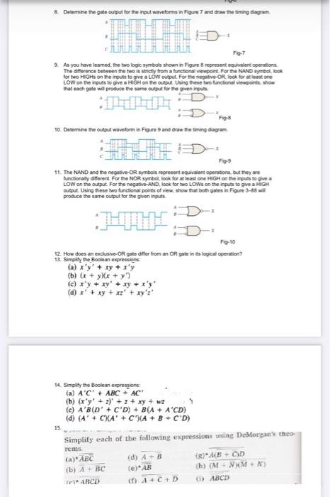
1. Determine the output, X, for a 2-input AND gate with the input waveforms shown in Figure-1. Show the proper relationship of output to inputs with a timing diagram. Repeat for 2 input OR gate. Fig-1 2. The waveforms in Figure-2 are applied to points A and B of a 2-input AND gate followed by an inverter. Draw the output waveform. Fig-2 3. Considering (Figure -2) A and B as two inputs, draw the output for 2 input OR gate, NOR gate, 4. The input waveforms applied to a 3-input AND gate are as indicated in Figure 3. Show the output waveform in proper relation to the inputs with a timing diagram. Repeat for 3 input OR gate Fig-3 5. The input waveforms applied to a 4-input AND gate are as indicated in Figure 4. The output of the AND gate is fed to an inverter. Draw the net output waveform of this system. Repeat for 4 input OR gate. Fig-4 6. For the waveforms given in Figure 5. A and B are ANDed with output F. D and E are ANDed with output G, and C.F. and Gare ORed. Draw the net output waveform. Fig.5 7. Show the truth table for a system of a 3-input OR gate followed by an inverter. For the set of input waveforms in Figure 6. determine the output for the gate shown and draw the timing diagram * Determine the gate output for the input waveforma n Figure 7 and the the Timing bugun F97 9. As you have leamed. the two logic symbols shown in Figure represent equivalent operations The difference between the two is strictly from a functional viewport. For the NAND symbol, look LOW on the inputs to give a HIGH on the output. Using these two functional viewpoints show that each gate will produce the same output for the given inputs Figs 10. Determine the output waveform in Figure and draw the timing dagam Figo 11. The NAND and the negative-OR symbols represent equivalent operations, but they are functionally different. For the NOR symbol, look for at least one HIGH on the inputs to give a LOW on the output. For the negative-AND, look for two LOW on the inputs to give a HIGH output Using these two functional point of view show that both gates in Figure 3-88 produce the same output for the given inputs F9-10 12. How does an exclusive OR gate differ from an OR patents logical operation? 13. Simply the Boolean expressions (a) xy + xy + s'y (b) (x + yXx + y) (c) xy + xy + xy + xy (d) x' + xy + xz' + ry':' 14. Simplify the Boolean expressions (a) A'C' + ABC - AC (b) (xy' + ' + : + xy + wz () AB(D' +C'D) + B(A + A'CD) (d) (A' + CXA' + C'XA + B + CD) 15 Simplify each of the following expressions using DeMorgan's theo rens (a) ABC (d) -B (AB+CD (b) ABC (e) AB (h) (M+M+N) ABCD (1) A+C+D (1) ABCD


