Answered step by step
Verified Expert Solution
Question
1 Approved Answer
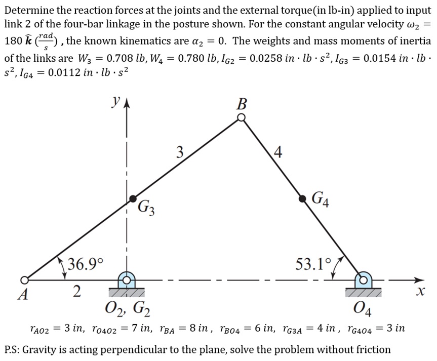
1 ) Draw the Free - Body Diagrams 2 ) Write the equations that describe the movements of the links 3 ) Determine the magnitudes
Draw the FreeBody Diagrams
Write the equations that describe the movements of the links
Determine the magnitudes and directions of the forces in the joints
Determine the magnitude and direction of Torque T
Determine the reaction forces at the joints and the external torquein lbin applied to input
link of the fourbar linkage in the posture shown. For the constant angular velocity
widehat the known kinematics are The weights and mass moments of inertia
of the links are
PS: Gravity is acting perpendicular to the plane, solve the problem without friction

Step by Step Solution
There are 3 Steps involved in it
Step: 1

Get Instant Access to Expert-Tailored Solutions
See step-by-step solutions with expert insights and AI powered tools for academic success
Step: 2

Step: 3

Ace Your Homework with AI
Get the answers you need in no time with our AI-driven, step-by-step assistance
Get Started


