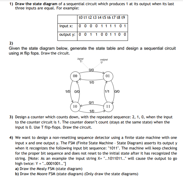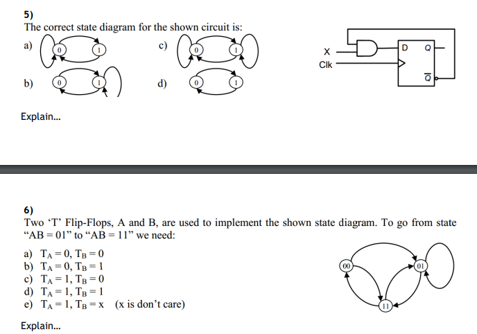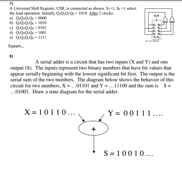


1) Draw the state diagram of a sequential circuit which produces 1 at its output when its last three inputs are equal. For example: to t1 t2 t3 t4 t5 t6 t7 t8t9 input x: 00001111 01 output y: 0 0 1 1 0 0 1 1 0 0 2) Given the state diagram below, generate the state table and design a sequential circuit using JK flip fops. Draw the circuit. inpur ow 7 0/0 00 01 1/0 1/0 0/0 (1/1 0/0 0/1 10 11 1/0 3) Design a counter which counts down, with the repeated sequence: 2, 1, 0, when the input to the counter circuit is 1. The counter doesn't count (stays at the same state) when the input is 0. Use T flip-flops. Draw the circuit. 4) We want to design a non-resetting sequence detector using a finite state machine with one input x and one output y. The FSM (Finite State Machine - State Diagram) asserts its output y when it recognizes the following input bit sequence: "1011". The machine will keep checking for the proper bit sequence and does not reset to the initial state after it has recognized the string. [Note: As an example the input string X= "..1011011.." will cause the output to go high twice: Y = "..0001001..") a) Draw the Mealy FSM (state diagram) b) Draw the Moore FSM (state diagram) (Only draw the state diagrams) 5) The correct state diagram for the shown circuit is: a) X Clk : b) d) Explain... 6) Two T' Flip-Flops, A and B, are used to implement the shown state diagram. To go from state "AB=01" to "AB = 11" we need: a) TA=0, TB = 0 b) TA=0, TB = 1 c) TA= 1, TB = 0 d) TA= 1, TB = 1 e) TA= 1, TB = x (x is don't care) Explain... CLK 7) A Universal Shift Register, USR, is connected as shown. Si=1, So =1 select the load operation. Initially Q:Q2Q.Qo = 1010. After 2 clocks: a) Q3Q2QQ0-0000 b) 0:Q.Q.Q. = 1010 c) Q:Q2Q.Qe = 0101 d) QQ2Q.Qo = 1001 e) Q3Q2QQo -1111 DQ DQ, DQ DQ, S, S Explain... 8) A serial adder is a circuit that has two inputs (X and Y) and one output (S). The inputs represent two binary numbers that have bit values that appear serially beginning with the lowest significant bit first. The output is the serial sum of the two numbers. The diagram below shows the behavior of this circuit for two numbers, X = ...01101 and Y = ... 11100 and the sum is S= ...01001. Draw a state diagram for the serial adder. X=10110 ... Y = 00111 .... + S=10010


