Question
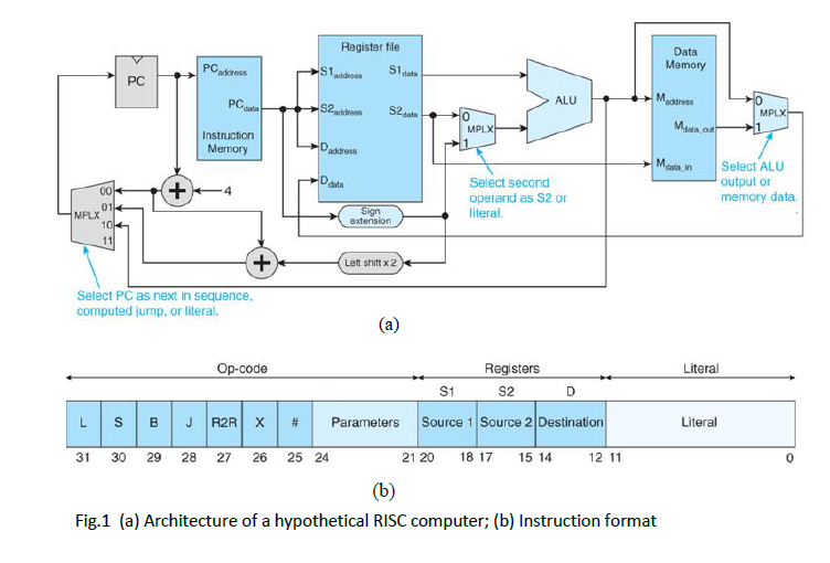
1. Fig. 1 shows the architecture of a RISC computer and its instruction format. The instrcutions are: Load (L), Store (S), Branch (B), Jump (J),
1. Fig. 1 shows the architecture of a RISC computer and its instruction format. The instrcutions are: Load (L), Store (S), Branch (B), Jump (J), Register-to-Register (R2R), and Reserved (X). Bit 25 is the literal bit. Some of typical operations are: LDR D,(S1,S2) [D] [M([S1] + [S2])] Register indirect with double indexing LDR D,(S1,#L) [D] [M([S1] + L)] Register indirect with literal offset STR (S1,#L),S2 [M([S1] + L)] [S2] Register indirect with literal offset ADD D,S1,S2 [D] [S1] + [S2] Register to register ADD D,S1,#L [D] [S1] + L Register to register with literal operand BEQ L [PC] [PC] + 4 + L This is a relative conditional branch
JMP (S1,#L)

Assume r1=2B0016, r2=C16, answer the following questions:
(2) 4-bit Parameters can be used to design 24 R2R instruction. Using these 4-bit parameters to design the following instructions. AND D,S1,S2 OR D,S1,S2 XOR D,S1,S2 And show the 32-bit number for AND r0,r1,r2 AND r0,r2,#15
Register file addeoss S S2addsss S2data Data Memory S1 PC ALU 0 Instruction Memory ala in Select ALU Select second operand as S2 or literal. output or memory data 4 MPLX Lett shift x2 Select PC as next in sequence computed jump, or literal. Registers S2 Literal S1 | S | B | J R2R| X | # | Parameters |Source 1|Source 2|Destination Literal 31 30 29 28 27 26 25 24 21 20 18 17 15 14 12 11 Fig.1 (a) Architecture of a hypothetical RISC computer; (b) Instruction format
Step by Step Solution
There are 3 Steps involved in it
Step: 1

Get Instant Access to Expert-Tailored Solutions
See step-by-step solutions with expert insights and AI powered tools for academic success
Step: 2

Step: 3

Ace Your Homework with AI
Get the answers you need in no time with our AI-driven, step-by-step assistance
Get Started


