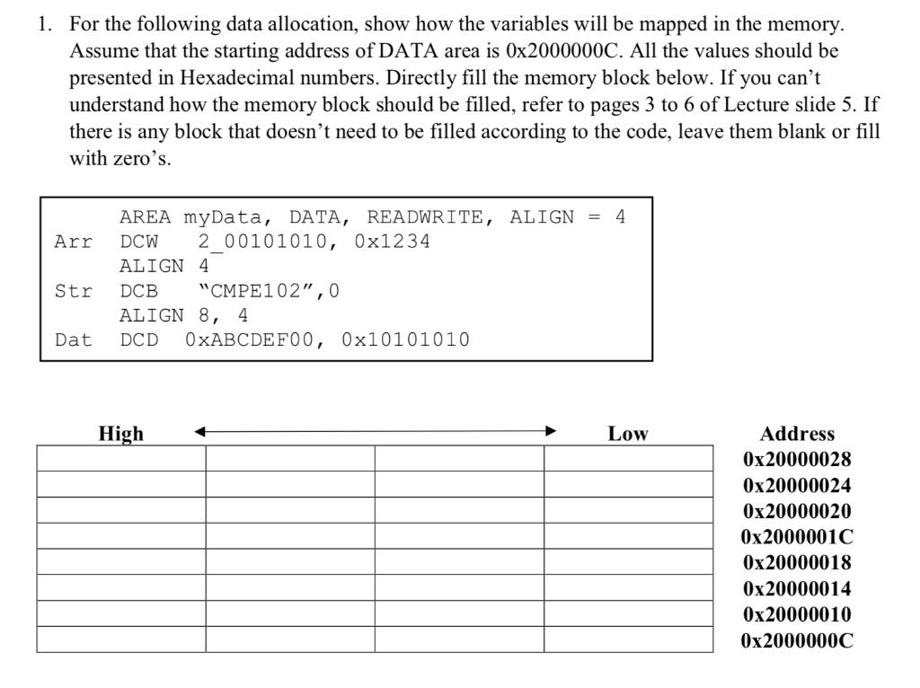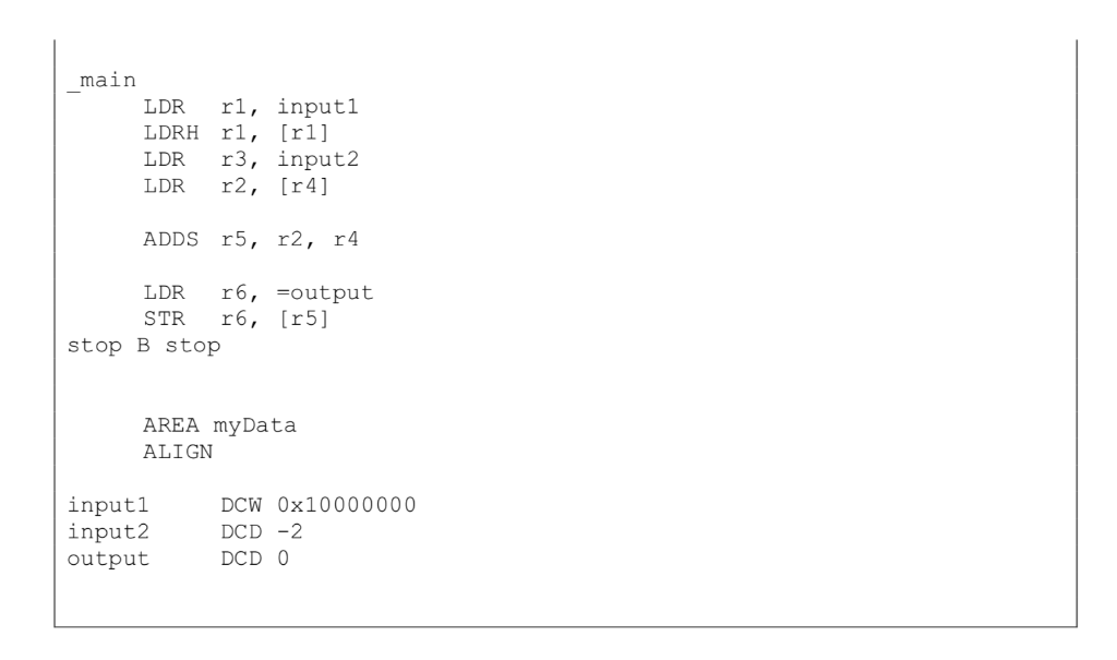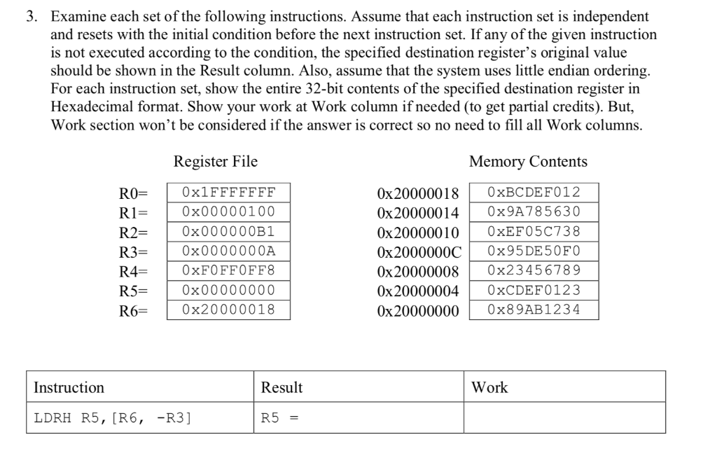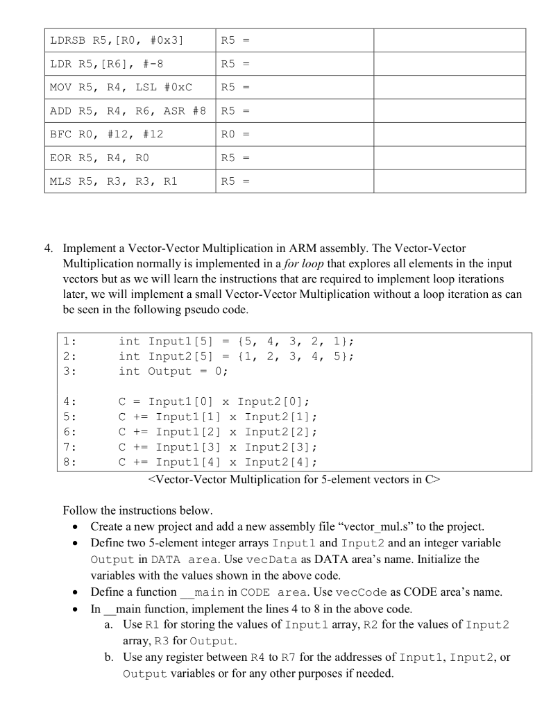


1. For the following data allocation, show how the variables will be mapped in the memory Assume that the starting address of DATA area is 0x2000000C. All the values should be presented in Hexadecimal numbers. Directly fill the memory block below. If you can't understand how the memory block should be filled, refer to pages 3 to 6 of Lecture slide 5. If there is any block that doesn't need to be filled according to the code, leave them blank or fill with zero's. Arr DCW 2 00101010, 0x1234 Str DCB "CMPE 1 02,, , 0 Dat DCD 0xABCDEFOO, 0x10101010 AREA myData, DATA, REA DWRITE, ALIGN 4 ALIGN 4 ALIGN 8, 4 Low Address 0x20000028 0x20000024 0x20000020 0x2000001C 0x20000018 0x20000014 0x20000010 0x2000000C You wanted to implement a code that adds two words like below. But, you found that the code has compilation errors. Show how the code should be fixed 2. AREA myCode ALIGN main LDR rl, inputl LDRH rl, [r1l LDR r3, input'2 LDR r2, [r4] ADDS r5, r2, r4 LDR r6,-output STR r6, [r5] stop B stop AREA myData ALIGN inputl input2 output DCW 0x10000000 DCD -2 DCD 0 3. Examine each set of the following instructions. Assume that each instruction set is independent and resets with the initial condition before the next instruction set. If any of the given instruction is not executed according to the condition, the specified destination register's original value should be shown in the Result column. Also, assume that the system uses little endian ordering For each instruction set, show the entire 32-bit contents of the specified destination register in Hexadecimal format. Show your work at Work column if needed (to get partial credits). But, Work section won't be considered if the answer is correct so no need to fill all Work columns Register File Memory Contents R00x1FFFFFFF R10x00000100 R2- R3 R4 0xFOFFOFF8 R5 R60x20000018 0x20000018 0xBCDEF012 0x200000140x9A785630 0x20000010 0xEF05C738 0x2000000C 0x95DE50FO 0x20000008 0x23456789 0x200000040xCDEF0123 0x20000000 0x89AB1234 0x000000B1 0x0000000A 0x00000000 Instruction Result Work LDRH R5, [R6,-R3] R5- LDRSBR5 , [R0 , #0x3] LDR R5, [R6 ], #-8 MOV R5, R4, LSL #OxC ADD R5, R4, R6, ASR #8 | R5- BFC R0, #12, #12 EOR R5, R4, RO MLS R5, R3, R3, R1 R5 = R0 = R5- R5 = 4. Implement a Vector-Vector Multiplication in ARM assembly. The Vector-Vector Multiplication normally is implemented in a for loop that explores all elements in the input vectors but as we will learn the instructions that are required to implement loop iterations later, we will implement a small Vcctor-Vcctor Multiplication without a loop itcration as carn be seen in the following pseudo code int Inputl [5] -(5, 4, 3, 2, 1); int Input2 [5] -1, 2, 3, 4, 5); int Output = 0; C = Input1 [0] x Input2 [0]; C += Input1 [1] x input2 [1]; C += Input 1 [2] x Input 2 [2] ; C += Input 1 [3] x Input2 [3] ; C += Input1 [4] x Input2 [4];
Follow the instructions below. Create a new project and add a new assembly file "vector mul.s" to the project Define two 5-clement integer arrays Inputl and Input2 and an integer variable Output in DATA area. Use vecData as DATA area's name. Initialize the variables with the values shown in the above code Define a function . main in CODE area. Use vecCode as CODE area's name In main function, implement the lines 4 to 8 in the above code Use R1 for storing the values of Inputl array, R2 for the values of Input2 array, R3 for Output a. b. Use any register between R4 to R7 for the addresses of Inputl, Input2, or Output variables or for any other purposes if needed. 1. For the following data allocation, show how the variables will be mapped in the memory Assume that the starting address of DATA area is 0x2000000C. All the values should be presented in Hexadecimal numbers. Directly fill the memory block below. If you can't understand how the memory block should be filled, refer to pages 3 to 6 of Lecture slide 5. If there is any block that doesn't need to be filled according to the code, leave them blank or fill with zero's. Arr DCW 2 00101010, 0x1234 Str DCB "CMPE 1 02,, , 0 Dat DCD 0xABCDEFOO, 0x10101010 AREA myData, DATA, REA DWRITE, ALIGN 4 ALIGN 4 ALIGN 8, 4 Low Address 0x20000028 0x20000024 0x20000020 0x2000001C 0x20000018 0x20000014 0x20000010 0x2000000C You wanted to implement a code that adds two words like below. But, you found that the code has compilation errors. Show how the code should be fixed 2. AREA myCode ALIGN main LDR rl, inputl LDRH rl, [r1l LDR r3, input'2 LDR r2, [r4] ADDS r5, r2, r4 LDR r6,-output STR r6, [r5] stop B stop AREA myData ALIGN inputl input2 output DCW 0x10000000 DCD -2 DCD 0 3. Examine each set of the following instructions. Assume that each instruction set is independent and resets with the initial condition before the next instruction set. If any of the given instruction is not executed according to the condition, the specified destination register's original value should be shown in the Result column. Also, assume that the system uses little endian ordering For each instruction set, show the entire 32-bit contents of the specified destination register in Hexadecimal format. Show your work at Work column if needed (to get partial credits). But, Work section won't be considered if the answer is correct so no need to fill all Work columns Register File Memory Contents R00x1FFFFFFF R10x00000100 R2- R3 R4 0xFOFFOFF8 R5 R60x20000018 0x20000018 0xBCDEF012 0x200000140x9A785630 0x20000010 0xEF05C738 0x2000000C 0x95DE50FO 0x20000008 0x23456789 0x200000040xCDEF0123 0x20000000 0x89AB1234 0x000000B1 0x0000000A 0x00000000 Instruction Result Work LDRH R5, [R6,-R3] R5- LDRSBR5 , [R0 , #0x3] LDR R5, [R6 ], #-8 MOV R5, R4, LSL #OxC ADD R5, R4, R6, ASR #8 | R5- BFC R0, #12, #12 EOR R5, R4, RO MLS R5, R3, R3, R1 R5 = R0 = R5- R5 = 4. Implement a Vector-Vector Multiplication in ARM assembly. The Vector-Vector Multiplication normally is implemented in a for loop that explores all elements in the input vectors but as we will learn the instructions that are required to implement loop iterations later, we will implement a small Vcctor-Vcctor Multiplication without a loop itcration as carn be seen in the following pseudo code int Inputl [5] -(5, 4, 3, 2, 1); int Input2 [5] -1, 2, 3, 4, 5); int Output = 0; C = Input1 [0] x Input2 [0]; C += Input1 [1] x input2 [1]; C += Input 1 [2] x Input 2 [2] ; C += Input 1 [3] x Input2 [3] ; C += Input1 [4] x Input2 [4]; Follow the instructions below. Create a new project and add a new assembly file "vector mul.s" to the project Define two 5-clement integer arrays Inputl and Input2 and an integer variable Output in DATA area. Use vecData as DATA area's name. Initialize the variables with the values shown in the above code Define a function . main in CODE area. Use vecCode as CODE area's name In main function, implement the lines 4 to 8 in the above code Use R1 for storing the values of Inputl array, R2 for the values of Input2 array, R3 for Output a. b. Use any register between R4 to R7 for the addresses of Inputl, Input2, or Output variables or for any other purposes if needed


