Answered step by step
Verified Expert Solution
Question
1 Approved Answer
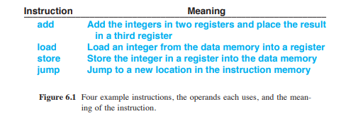
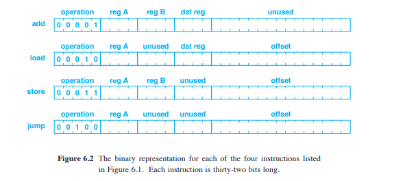
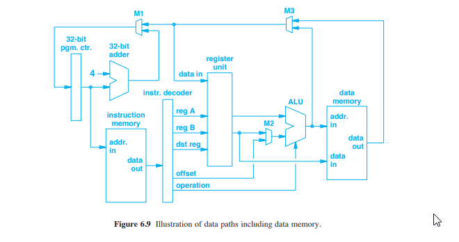
1. Given the instruction set of Figures 6.1 and 6.2, how many bits wide must the operation bus be where it enters the ALU in


1. Given the instruction set of Figures 6.1 and 6.2, how many bits wide must the operation bus be where it enters the ALU in Figure 6.9? (This question is asking for the minimum number of bits that will allow correct operation of the circuit. Padding bits can always be added to any encoded bit string representation.)
Meaning Add the integers in two registers and place the result Instruction add in a third register load store Store the integer in a register into the data memory ump Jump to a new location in the instruction memory Load an integer from the data memory into a register Figure 6.1 Four example instructions, the operandseach uses,and the mean- ing of the instruction operation reg A reg B dst reg unused add 0 0001 operation reg A unused dst reg offset load o 001 operation reg A reg B unused offset store o 001 operation reg A unused unused offset ump o 01 0 0 Figure 6.2 The binary representation for each of the four instructions listed in Figure 6.1. Each instruction is thirty-two bits long M1 M3 32-bit pgm. ctr 32-bit register unit 4 data in instr. decoder data ALU reg A reg B dst instruction M2 in data out in data out data in operation Figure 6.9 ustration of data paths including data memory Meaning Add the integers in two registers and place the result Instruction add in a third register load store Store the integer in a register into the data memory ump Jump to a new location in the instruction memory Load an integer from the data memory into a register Figure 6.1 Four example instructions, the operandseach uses,and the mean- ing of the instruction operation reg A reg B dst reg unused add 0 0001 operation reg A unused dst reg offset load o 001 operation reg A reg B unused offset store o 001 operation reg A unused unused offset ump o 01 0 0 Figure 6.2 The binary representation for each of the four instructions listed in Figure 6.1. Each instruction is thirty-two bits long M1 M3 32-bit pgm. ctr 32-bit register unit 4 data in instr. decoder data ALU reg A reg B dst instruction M2 in data out in data out data in operation Figure 6.9 ustration of data paths including data memoryStep by Step Solution
There are 3 Steps involved in it
Step: 1

Get Instant Access to Expert-Tailored Solutions
See step-by-step solutions with expert insights and AI powered tools for academic success
Step: 2

Step: 3

Ace Your Homework with AI
Get the answers you need in no time with our AI-driven, step-by-step assistance
Get Started


