Question
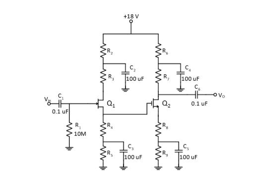
1) In the figure below there is an amplifier circuit obtained using JFET and MOSFET. For the FET used in the circuit, IDSS = 8
1) In the figure below there is an amplifier circuit obtained using JFET and MOSFET. For the FET used in the circuit, IDSS = 8 mA, VGSoff = -3V and working point current is 1.42 mA. MOSFET parameters are given as Kn = 1mA / V2, VTN = 1V, gm = 0.75 mA / V. The voltage gain of the first floor in the circuit is calculated as 0.7, and the voltage gain of the second floor is calculated as -40. It is given as R7 = 101R8. According to this; Determine the resistance values in the circuit to be KΩ (R2 = R3 = 2K.)

+18 V 100 uF R, 100 uF C. Vo Q2 0.1 uF 0.1 uF R, 10M _C, C, 100 uF 100 uF
Step by Step Solution
3.47 Rating (150 Votes )
There are 3 Steps involved in it
Step: 1
Solution The a...
Get Instant Access to Expert-Tailored Solutions
See step-by-step solutions with expert insights and AI powered tools for academic success
Step: 2

Step: 3

Ace Your Homework with AI
Get the answers you need in no time with our AI-driven, step-by-step assistance
Get StartedRecommended Textbook for
Fundamentals Of Momentum Heat And Mass Transfer
Authors: James Welty, Gregory L. Rorrer, David G. Foster
6th Edition
1118947460, 978-1118947463
Students also viewed these Electrical Engineering questions
Question
Answered: 1 week ago
Question
Answered: 1 week ago
Question
Answered: 1 week ago
Question
Answered: 1 week ago
Question
Answered: 1 week ago
Question
Answered: 1 week ago
Question
Answered: 1 week ago
Question
Answered: 1 week ago
Question
Answered: 1 week ago
Question
Answered: 1 week ago
Question
Answered: 1 week ago
Question
Answered: 1 week ago
Question
Answered: 1 week ago
Question
Answered: 1 week ago
Question
Answered: 1 week ago
Question
Answered: 1 week ago
Question
Answered: 1 week ago
Question
Answered: 1 week ago
Question
Answered: 1 week ago
Question
Answered: 1 week ago
Question
Answered: 1 week ago
Question
Answered: 1 week ago
Question
Answered: 1 week ago
View Answer in SolutionInn App


