Answered step by step
Verified Expert Solution
Question
1 Approved Answer
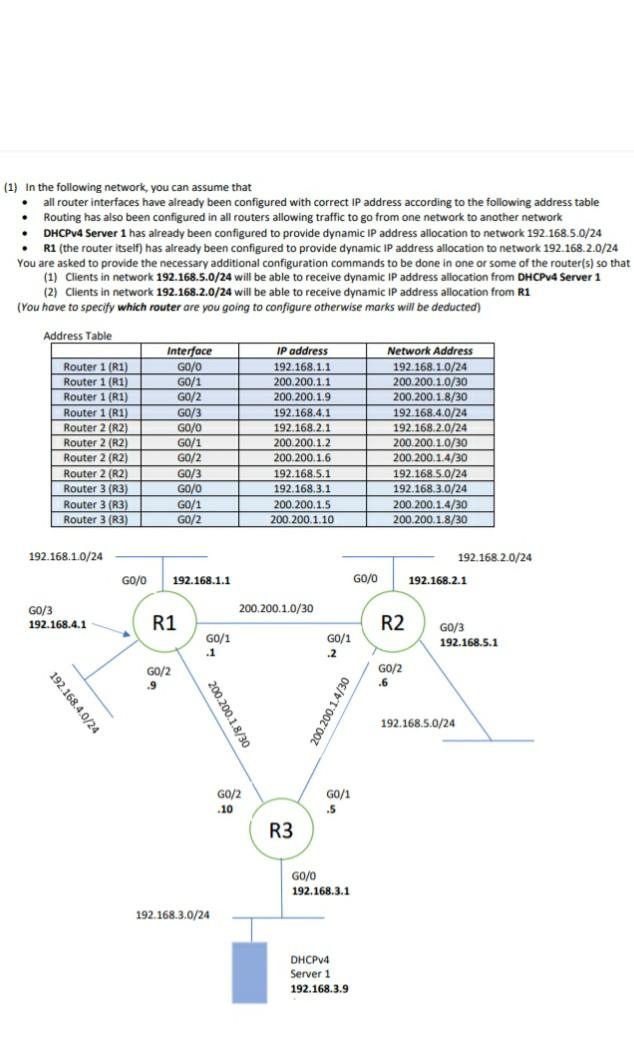
(1) In the following network, you can assume that all router interfaces have already been configured with correct IP address according to the following address


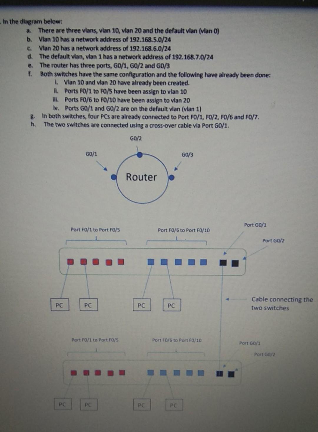
(1) In the following network, you can assume that all router interfaces have already been configured with correct IP address according to the following address table Routing has also been configured in all routers allowing traffic to go from one network to another network DHCPv4 Server 1 has already been configured to provide dynamic IP address allocation to network 192.168.5.0/24 R1 (the router itself) has already been configured to provide dynamic IP address allocation to network 192.168.2.0/24 You are asked to provide the necessary additional configuration commands to be done in one or some of the router(s) so that (1) Clients in network 192.168.5.0/24 will be able to receive dynamic IP address allocation from DHCPv4 Server 1 (2) Clients in network 192.168.2.0/24 will be able to receive dynamic IP address allocation from R1 (You have to specify which router are you going to configure otherwise marks will be deducted) Address Table Router 1 (R1) Router 1 (R1) Router 1 (R1) Router 1 (R1) Router 2 (R2) Router 2 (R2) Router 2 (R2) Router 2 (R2) Router 3 (R3) Router 3 (R3) Router 3 (R3) Interface GO/0 GO/1 GO/2 GO/3 GO/O GO/1 GO/2 GO/3 GO/O GO/1 GO/2 IP address 192.168.1.1 200.200.1.1 200,200.1.9 192.168.4.1 192.168.2.1 200.200.1.2 200,200.1.6 192.168.5.1 192.168.3.1 200.200.1.5 200.200.1.10 Network Address 192.168.1.0/24 200.200.1.0/30 200.200.1.8/30 192.168.4.0/24 192.168.2.0/24 200.200.1.0/30 200.200.1.4/30 192.168.5.0/24 192.168.3.0/24 200.200.1.4/30 200.200.1.8/30 192.168.1.0/24 192.168.2.0/24 192.168.2.1 GO/O 192.168.1.1 G0/0 GO/3 200.200.1.0/30 192.168.4.1 R1 R2 G0/1 .1 G0/1 .2 G0/3 192.168.5.1 G0/2 .9 GO/2 .6 192.168.4.0/24 200.200.1.8/30 200 200.1.4/30 192.168.5.0/24 G0/2 G0/1 .5 -10 R3 GO/O 192.168.3.1 192.168.3.0/24 DHCPv4 Server 1 192.168.3.9 C In the diagram below: a. There are three vlans, vlan 10, vlan 20 and the default vlan (vlan o) b. Vlan 10 has a network address of 192.168.5.0/24 Vlan 20 has a network address of 192.168.6.0/24 d. The default vlan, vlan 1 has a network address of 192.168.7.0/24 e. The router has three ports, G0/1, GO/2 and G0/3 f. Both switches have the same configuration and the following have already been done: 1. Vlan 10 and vlan 20 have already been created. II. Ports F0/1 to FO/have been assign to vlan 10 ill. Ports F0/6 to FO/10 have been assign to vlan 20 Iv. Ports G0/1 and G0/2 are on the default vlan (vlan 1) In both switches, four PCs are already connected to Port FO/1, FO/2, F0/6 and F0/7. h. The two switches are connected using a cross-over cable via Port G0/1. G0/2 G0/1 G0/3 Router Port G0/1 Port FO/1 to Port FO/5 Port F0/6 to Port FO/10 Port G0/2 PC PC PC PC Cable connecting the two switches Port Fo/1 to Port F0/5 Port FO/6 to Port F0/10 Port G0/1 Port G0/2 PC PC PC PC
Step by Step Solution
There are 3 Steps involved in it
Step: 1

Get Instant Access to Expert-Tailored Solutions
See step-by-step solutions with expert insights and AI powered tools for academic success
Step: 2

Step: 3

Ace Your Homework with AI
Get the answers you need in no time with our AI-driven, step-by-step assistance
Get Started


