Answered step by step
Verified Expert Solution
Question
1 Approved Answer
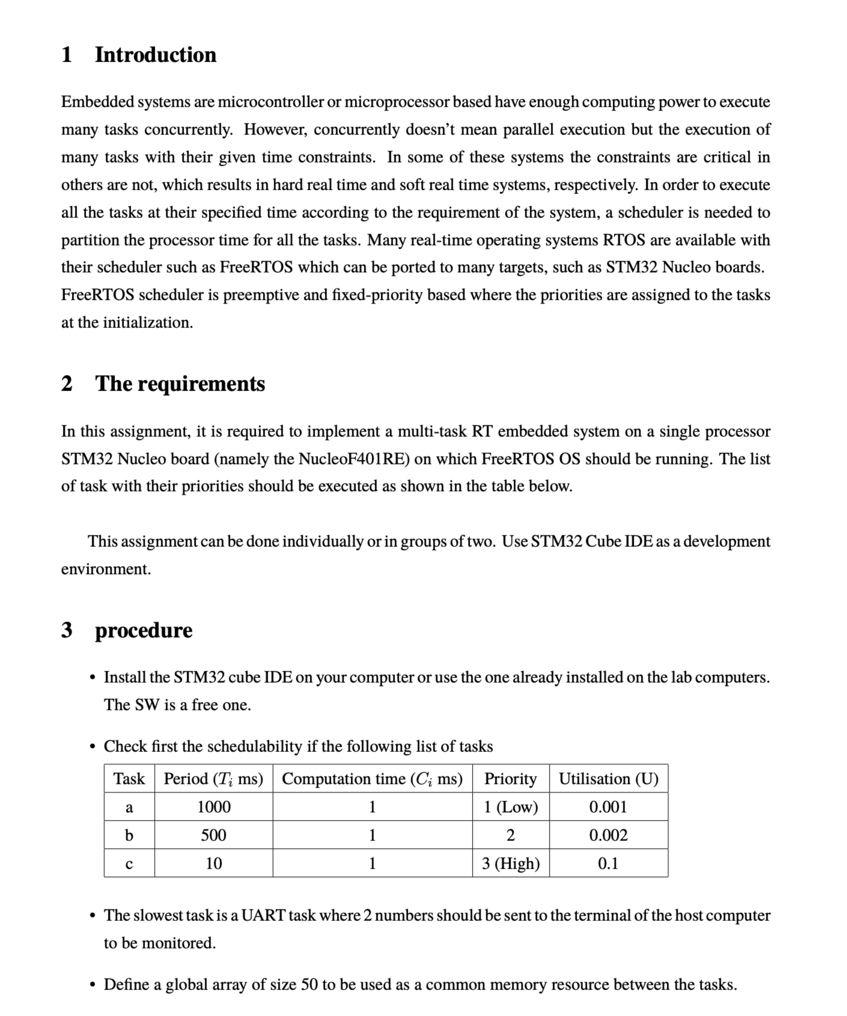
1 Introduction Embedded systems are microcontroller or microprocessor based have enough computing power to execute many tasks concurrently. However, concurrently doesn't mean parallel execution but
Introduction
Embedded systems are microcontroller or microprocessor based have enough computing power to execute
many tasks concurrently. However, concurrently doesn't mean parallel execution but the execution of
many tasks with their given time constraints. In some of these systems the constraints are critical in
others are not, which results in hard real time and soft real time systems, respectively. In order to execute
all the tasks at their specified time according to the requirement of the system, a scheduler is needed to
partition the processor time for all the tasks. Many realtime operating systems RTOS are available with
their scheduler such as FreeRTOS which can be ported to many targets, such as STM Nucleo boards.
FreeRTOS scheduler is preemptive and fixedpriority based where the priorities are assigned to the tasks
at the initialization.
The requirements
In this assignment, it is required to implement a multitask RT embedded system on a single processor
STM Nucleo board namely the NucleoFRE on which FreeRTOS OS should be running. The list
of task with their priorities should be executed as shown in the table below.
This assignment can be done individually or in groups of two. Use STM Cube IDE as a development
environment.
procedure
Install the STM cube IDE on your computer or use the one already installed on the lab computers.
The SW is a free one.
Check first the schedulability if the following list of tasks
The slowest task is a UART task where numbers should be sent to the terminal of the host computer
to be monitored.
Define a global array of size to be used as a common memory resource between the tasks. The fastest task ie task c generate a sequence of random numbers you may benefit from the
example of code snippet given below The numbers should be passed to the task using a
Mutexe so that no other task can change the global array before filling it completely by the task c
In task b the average will be found and passed to task a through another global array of size two.
The task a then sends the two average temperatures to the terminal using the UART for moni
toring. Along with this operation the task should toggle the green LED on the board each time the
task is executed.
For each one of the tasks and define a GPIO output to show the start and the end of the task
execution as follows. When the task starts to execute the GPIO is SET and whe the execution is
finished the GPIO is RESET. This will help with the use of an oscilloscope to observe the different
task execution times Deliverable
In a report, explain the procedure you followed and the results you obtained.
Show the figures of the scheduler test with the oscilloscope.
From the oscilloscope monitoring, show how much processor power is used?
show a snapshot of the terminal where the average temperature is monitored. In this assignment, it is required to implement a multitask RT embedded system on a single processor on
which Arduino OS should be running. The list
of task with their priorities should be executed as shown in the table below.
The slowest task is a UART task where numbers should be sent to the terminal of the host computer
to be monitored.
Define a global array of size to be used as a common memory resource between the tasks.
The fastest task ie task c generate a sequence of random numbers you may benefit from the
example of code snippet given below The numbers should be passed to the task using a
Mutexe so that no other task can change the global array before filling it completely by the task
In task the average will be found and passed to task a through another global array of size two.
The task a then sends the two average temperatures to the terminal using the UART for monitoring.
Along with this operation the task should toggle the green LED on the board each time the
task is executed.
For each one of the tasks and define a GPIO output to show the start and the end of the task
execution as follows. When the task starts to execute the GPIO is SET and when the execution is
finished the GPIO is RESET. This will help with the use of an oscilloscope to observe the different
task execution times Ci
NOTE : write the code with thies requirments but for arduino IDE, in order to run with ONU bord

Step by Step Solution
There are 3 Steps involved in it
Step: 1

Get Instant Access to Expert-Tailored Solutions
See step-by-step solutions with expert insights and AI powered tools for academic success
Step: 2

Step: 3

Ace Your Homework with AI
Get the answers you need in no time with our AI-driven, step-by-step assistance
Get Started


