

Answered step by step
Verified Expert Solution
Question
1 Approved Answer
1 MUO- A Very Simple Processor Program Counter Instruction Register CPU address bus Memory control control PC IR address memory ALU ACC latapath data Arithmetic
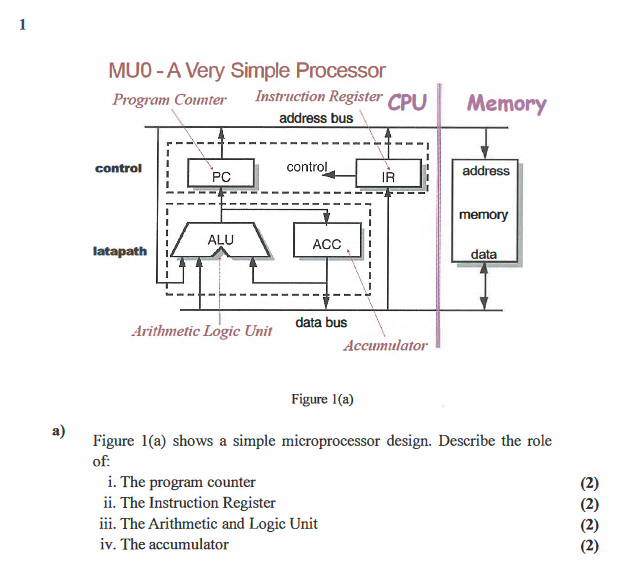
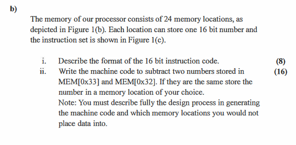
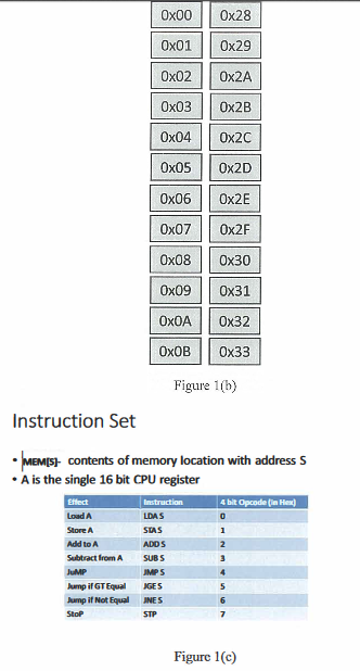
1 MUO- A Very Simple Processor Program Counter Instruction Register CPU address bus Memory control control PC IR address memory ALU ACC latapath data Arithmetic Logic Unit data bus Accumulator Figure 1(a) a) Figure 1(a) shows a simple microprocessor design. Describe the role of: i. The program counter ii. The Instruction Register iii. The Arithmetic and Logic Unit iv. The accumulator b) The memory of our processor consists of 24 memory locations, as depicted in Figure 1(b). Each location can store one 16 bit number and the instruction set is shown in Figure 1(c). (8) (16) i. Describe the format of the 16 bit instruction code. ii. Write the machine code to subtract two numbers stored in MEM[0x33] and MEM[0x32]. If they are the same store the number in a memory location of your choice. Note: You must describe fully the design process in generating the machine code and which memory locations you would not place data into. Ox00 Ox28 Ox01 Ox29 Ox02 Ox2A Ox03 0x2B Ox04 0x2C Ox05 Ox2D Ox06 Ox2E Ox07 Ox2F Ox08 Ox30 Ox09 Ox31 0x32 OXOA Ox 0x33 Figure 1(b) Instruction Set MEMS: contents of memory location with address S A is the single 16 bit CPU register Instruction LDAS SIAS ADDS SUBS 4 bit Opcode in het 0 1 Effect Load A Store A Add to Subtract from A JUMP Jump if GT Equal Jump if Not Equal Stop 2 4 5 MPS GES INES STP 6 Figure 1(c) 1 MUO- A Very Simple Processor Program Counter Instruction Register CPU address bus Memory control control PC IR address memory ALU ACC latapath data Arithmetic Logic Unit data bus Accumulator Figure 1(a) a) Figure 1(a) shows a simple microprocessor design. Describe the role of: i. The program counter ii. The Instruction Register iii. The Arithmetic and Logic Unit iv. The accumulator b) The memory of our processor consists of 24 memory locations, as depicted in Figure 1(b). Each location can store one 16 bit number and the instruction set is shown in Figure 1(c). (8) (16) i. Describe the format of the 16 bit instruction code. ii. Write the machine code to subtract two numbers stored in MEM[0x33] and MEM[0x32]. If they are the same store the number in a memory location of your choice. Note: You must describe fully the design process in generating the machine code and which memory locations you would not place data into. Ox00 Ox28 Ox01 Ox29 Ox02 Ox2A Ox03 0x2B Ox04 0x2C Ox05 Ox2D Ox06 Ox2E Ox07 Ox2F Ox08 Ox30 Ox09 Ox31 0x32 OXOA Ox 0x33 Figure 1(b) Instruction Set MEMS: contents of memory location with address S A is the single 16 bit CPU register Instruction LDAS SIAS ADDS SUBS 4 bit Opcode in het 0 1 Effect Load A Store A Add to Subtract from A JUMP Jump if GT Equal Jump if Not Equal Stop 2 4 5 MPS GES INES STP 6 Figure 1(c)
Step by Step Solution
There are 3 Steps involved in it
Step: 1

Get Instant Access to Expert-Tailored Solutions
See step-by-step solutions with expert insights and AI powered tools for academic success
Step: 2

Step: 3
Ace Your Homework with AI
Get the answers you need in no time with our AI-driven, step-by-step assistance
Get Started
Main Memory Database Systems
Authors: Frans Faerber, Alfons Kemper, Per-Åke Alfons
1st Edition
1680833243, 978-1680833249