Question
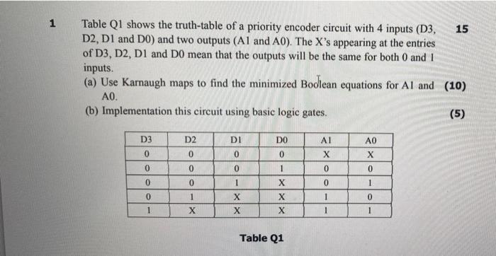
1 Table Q1 shows the truth-table of a priority encoder circuit with 4 inputs (D3, D2, D1 and D0) and two outputs (A1 and

1 Table Q1 shows the truth-table of a priority encoder circuit with 4 inputs (D3, D2, D1 and D0) and two outputs (A1 and A0). The X's appearing at the entries of D3, D2, D1 and D0 mean that the outputs will be the same for both 0 and 1 inputs. (a) Use Karnaugh maps to find the minimized Bodlean equations for Al and (10) AO. (b) Implementation this circuit using basic logic gates. D3 0 0 0 0 1 D2 0 0 0 1 X DI 0 0 1 X X DO 0 1 X X X Table Q1 Al X 0 0 1 I A0 X 0 1 0 1 15 (5)
Step by Step Solution
3.39 Rating (155 Votes )
There are 3 Steps involved in it
Step: 1

Get Instant Access to Expert-Tailored Solutions
See step-by-step solutions with expert insights and AI powered tools for academic success
Step: 2

Step: 3

Ace Your Homework with AI
Get the answers you need in no time with our AI-driven, step-by-step assistance
Get StartedRecommended Textbook for
Computer System Architecture
Authors: M. Morris Mano
3rd Edition
0131755633, 978-0131755635
Students also viewed these Computer Network questions
Question
Answered: 1 week ago
Question
Answered: 1 week ago
Question
Answered: 1 week ago
Question
Answered: 1 week ago
Question
Answered: 1 week ago
Question
Answered: 1 week ago
Question
Answered: 1 week ago
Question
Answered: 1 week ago
Question
Answered: 1 week ago
Question
Answered: 1 week ago
Question
Answered: 1 week ago
Question
Answered: 1 week ago
Question
Answered: 1 week ago
Question
Answered: 1 week ago
Question
Answered: 1 week ago
Question
Answered: 1 week ago
Question
Answered: 1 week ago
Question
Answered: 1 week ago
Question
Answered: 1 week ago
Question
Answered: 1 week ago
Question
Answered: 1 week ago
Question
Answered: 1 week ago
View Answer in SolutionInn App


